Download
1 / 8
80 likes | 85 Vues
Iterative Interference Cancellation for a PB/MC-CDMA System with MMSE-FDE in the Downlink Kyujin Lee, Kyesan Lee, Kyung Hee University, 1 Seocheon-dong, Giheung-gu, Yongin-si, Gyeonggi-do, 446-701, Republic of Korea {kyujin, kyesan}@ khu.ac.kr

E N D
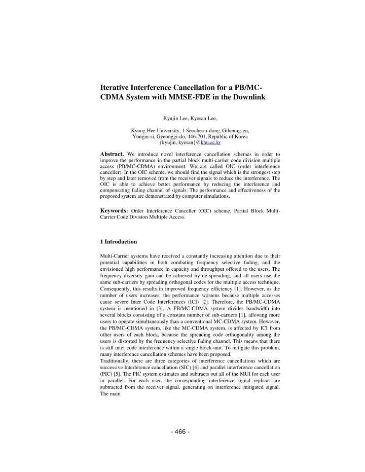
Iterative Interference Cancellation for a PB/MC-CDMA System with MMSE-FDE in the Downlink Kyujin Lee, Kyesan Lee, Kyung Hee University, 1 Seocheon-dong, Giheung-gu, Yongin-si, Gyeonggi-do, 446-701, Republic of Korea {kyujin, kyesan}@khu.ac.kr Abstract. We introduce novel interference cancellation schemes in order to improve the performance in the partial block multi-carrier code division multiple access (PB/MC-CDMA) environment. We are called OIC (order interference canceller). In the OIC scheme, we should find the signal which is the strongest step by step and later removed from the receiver signals to reduce the interference. The OIC is able to achieve better performance by reducing the interference and compensating fading channel of signals. The performance and effectiveness of the proposed system are demonstrated by computer simulations. Keywords: Order Interference Canceller (OIC) scheme, Partial Block Multi-Carrier Code Division Multiple Access. 1 Introduction Multi-Carrier systems have received a constantly increasing attention due to their potential capabilities in both combating frequency selective fading, and the envisioned high performance in capacity and throughput offered to the users. The frequency diversity gain can be achieved by de-spreading, and all users use the same sub-carriers by spreading orthogonal codes for the multiple access technique. Consequently, this results in improved frequency efficiency [1]. However, as the number of users increases, the performance worsens because multiple accesses cause severe Inter Code Interferences (ICI) [2]. Therefore, the PB/MC-CDMA system is mentioned in [3]. A PB/MC-CDMA system divides bandwidth into several blocks consisting of a constant number of sub-carriers [1], allowing more users to operate simultaneously than a conventional MC-CDMA system. However, the PB/MC-CDMA system, like the MC-CDMA system, is affected by ICI from other users of each block, because the spreading code orthogonality among the users is distorted by the frequency selective fading channel. This means that there is still inter code interference within a single block-unit. To mitigate this problem, many interference cancellation schemes have been proposed. Traditionally, there are three categories of interference cancellations which are successive Interference cancellation (SIC) [4] and parallel interference cancellation (PIC) [5]. The PIC system estimates and subtracts out all of the MUI for each user in parallel. For each user, the corresponding interference signal replicas are subtracted from the receiver signal, generating on interference mitigated signal. The main - 466 -
advantage of PIC is its fastness. But it suffers from the disadvantage that lower power users will have their BER very high, since detection is done with less SIR and hardware complexity of receiver is high which requires a large number of cancellations. Hence, the performance of PIC is inferior to SIC. In this paper, we propose the interference cancellation scheme for PB/MC-CDMA system. The proposed system is the ordered interference cancellation (OIC). First, the OIC scheme is to sort in ascending order of the users signals which we look upon them as interference. In OIC, the signal with the largest power is regenerated and subtracted from total received signal and updating it. The remaining signals are now re-estimated and a new largest user is selected and the process continues until all the users’ signals have been recovered or the maximum allowable number of cancellations is reached. In OIC scheme, we should find the signal which is the strongest step by step and removed from the receiver signals, from that we know the OIC is very related with the final signal power, that is very sensitive to the receive signal power distribution and it favors unequal receive power. So at the transmitter we used the pre-weights among different users before the signals transmitting, at the same time, we used the OIC to cancel the interference from other users at the receiver and here Minimum mean square error (MMSE) [6] is also employed to suppress interference with the assumption of the perfect channel state information (CSI) at the receiver and reliable feedback of weight value distribution from the receiver to the transmitter. 2 Proposed System Description Fig. 1. Transmitter of the proposed PB/MC-CDMA system The transmitter structure for the PB/MC-CDMA with proposed OIC is illustrated in Fig. 1. Firstly, at the transmitter, a binary data sequence is transformed into data- µ u −1 * µ 1* µ 0* - 467-
modulated symbol sequence and then the total bandwidth is divided into B sub-blocks and each block has K sub-carriers yielding a total subcarrier number Nc = KB . Each user is assigned to a th b block. Here we assume one user used per single block. Then the data is spread using the u-th orthogonal spreading code { ( ) cu k ;u = 0 ~ U −1;k =0 ~ SF −1} which reused the spreading code in each block, here SF is the spreading factor and x denotes the largest integer that is not greater than x. Then the pilot symbols are inserted into the spread signals and also the spread signals are weighted by each users’ weights in order to maximize the signal to noise ratio (SNR) at the receiver. In this paper, the weight µu is the previous channel information from the receiver to the transmitter. At the first time, maximum ratio combing (MRC) method is used for weight derivation algorithm at the transmitter. So the k-th sub-carrier component of the data symbol stream can be expressed as U− 1 * S k ( ) = ∑ 2P µ d cϕ k SF ( ( )( )) mod . (1) u , k u u , Bu= 0 Where P =Ec (SF⋅ Tc) is the transmit power per spreading code with Ec being the signal energy per FFT sample and Tc being the FFT sample length. µu ,k is the estimated channel of the u-th user and the k-th subcarrier. * means the complex conjugate. After the U-order code multiplexing, the time domain PB/MC-CDMA signal is generated by applying N c -point inverse fast Fourier transform (IFFT) as After the insertion of cyclic prefix (CP) into the guard interval (GI), the PB/MC-CDMA signal is transmitted from the antenna. Assuming that channel has L independent propagation paths with chip-spaced distinct time delays, the impulse response h(t) of the channel can be expressed as [7] L − 1 h t ( ) = ∑ ( − ) h δ t τ = 0 Where hl and τl are the l-th path gain and time delay, respectively, with L− 1 ∑E[hl 2j =1 (here, EN is the ensemble average operation and δ(⋅) is the deltal=0 function). After removing the GI, which in Fig. 2, the received signal r(t) can be expressed as L− 1 r t ( )=∑h s(t − τ )+ η (t ) . (4) l l l=0 Where η(t) represents the zero-mean noise process having variance 2N0 Tc with N0 representing the single – sided power spectrum density of the additive white Gaussian noise (AWGN). Then the received signal is decomposed into Nc -point FFT. The k-th sub-carrier component of the received signal, then the R(k) can express as . (3) l - 468 -
Where H(k) and Π(k) are respectively the Fourier transforms of the channel impulse response and the noise and are given by Then the cancellation technique is mentioned, which to cancel the interference from other users. Start Fig. 2. The flowchart of the OIC at the receiver The Fig. 2. shows the flowchart of the OIC at the receiver. The operations are as follow: Step 1: calculating the received SNR for all the users. Step 2: comparing the obtained SNR value and ordering the users in descending order according to the SNR value. Step 3: storing the total received signal and updating it by subtracting the interference signal. Step 4: detecting the user’s signal from the currently stored received signal following the sequence mentioned in step 2, and the largest power signal can be detected. Received SNR calculation for users user data of largest power detection Ordering function Desire signal = current signal ? Yes No Total signal storing and updating Subtract from the total signal Interference generation current signal output End - 469 -
Step 5: checking whether the detected signal is the desired signal or not. If it is the desired signal then we have the output signal and the process is finished. If it is not the desired signal, then continue the iteration from step 3 to step5 until the desired user’s signal is detected. In order to describe the canceller part in detail, the following part is mentioned. In order to describe the cancellation part in detail, the following paragraphs are used. Fig. 3. PB/MC-CDMA receiver using joint MMSE-FDE and ICI cancellation The PB/MC-CDMA receiver using joint MMSE-FED and ICI cancellation is shown in Fig. 3. First of all, R(k) is the signal after the FFT. At the equalization part, we should use the channel estimation to get the desired signals. In this paper, we use the minimum mean square error frequency-domain equalization for reducing the ICI while minimizing the noise enhancement. So the signals after the equalization can express as follows: R%(k) = w(k)⋅ R(k) . (7) Here the w(k) is the weight of the MMSE which is given by [6] −1 2 E U N s + + 1 g N SF N 0 c Where H(k) is channel state information of k -th sub-carrier. After the equalization, the whole signal is de-spread to get the frequency diversity data because of the multi-carrier of every user. However, the presence of residual ICI after MMSE-FDE degrades achievable BER performance in frequency-selective fading channel. So we perform the OIC for reducing the residual ICI. To perform the OIC, we should select the maximum strength user U max through channel state information which is looked as the interference to re-spread to get % gu (k) and subtract from the receiver. Rˆ(k) =R(k)−g%u(k) . (9) H k * ( ) w k ( ) = (8) H k ( ) - 470 -
This is preceded by an operation that order according to the received signal strength. Also, the detection and cancellation process is achieved successively in order of strength. This process is repeated until desire users have been detected. The scheme is limited in complexity because only a user is removed in each cancellation. However, this approach leads to long delays when the number of users increases. Ru⇒R(3) = R(3)−g%1 + g% 2d ˆ g%1 As show in equation (10), we have divided the received power into different levels, each user has different power levels by pre-weight at the transmitter. More details will be described as follows: Step 1: We calculate the received SNR for all the users. Step 2: We compare the obtained SNR value and ordering these users in descending turn according to the SNR value. Step 3: as the level operation, the first strongest, the second strongest and the ( n −1) th strongest signal power which are larger than desired signal power should be subtracted from the receiver. Then, the follow interference canceller will be used. R(n)= R(n)− • • • — 1 Where g%n is the interference of n-th interferer to the desired user with the power level n. For example, if the received SNR order of desire user is 3, then the interference will be operated like (3) (3) 1 Rˆ = R − g % − g % , the first largest and second largest 2 received SNR as interference to subtract from the total receive signal to finish the process. From the above operation, we know that the interference is sorted by order, which means we just consider the interference from other users which have larger signal power than the desired user, so the OIC is get. At the same time the channel information should be saved and be feedback to the transmitter for the next propagating weights. Finally, the desired signal can be obtained through frequency domain dispreading We obtain the frequency diversity data du due to the multi-carrier. Here, Na = (user%B) where Nc B = SF 1) ˆ R ( R(1) 0 R (2) R(2) (10) n (n) g R( ) R k1+ 2+g %+ L+g % 3 n− 1 . Thus, finally we acquired the desired data. - 471 -
3 Simulation Parameters and Results Through computer simulations, we prove the advantages of our proposed system. The simulation parameters are shown in Table 1. Both the number of users and the FFT point are 128, the guard interval is 25% as compared to the symbol duration. In one OFDM frame, the symbol number and pilot number are 64 and 4, respectively. Also, the number of iteration of proposed system is from 0 to 3, which provides sufficiently improved BER performance. Table 1. Simulation parameters Subcarrier number 128 FFT point 128 Number of user nodes 2 Symbol number in one frame 64 Pilot number 4 Channel model 18-path Rayleigh fading channel Modulation type QPSK Guard Interval 0.25 (25% compared to symbol duration) SNR[dB] Fig. 4. BER performance comparisons of proposed system and conventional systems with iterative OIC scheme. The simulated BER performance with iterative OIC scheme is plotted in Fig. 4. with the number i of iterations. We use the spreading factor SF=32 and 32users and Doppler frequency 30Hz. The BER performance of the OIC scheme is better than BER performance of the PIC scheme, because OIC detection/cancellation is successively performed according to the descending order of the signal’ reliability. The iterative OIC can significantly improve the BER performance, while the BER of without iterative OIC worse than iterative OIC due to the residual ICI. When increasing the iterative number, proposed system can achieve the better performance. 0 2 4 6 8 10 12 14 16 18 20 BER 10-1 10-2 10-3 10-4 10-5 100 QPSK SF=32, 32users Doppler frequency=30Hz Number of iteration with OIC i=1 i=2 i=3 without OIC with PIC Iteration with OIC without OIC with PIC - 472 -
However, we can show that the more iterative number increase, the less BER performance is little improved, because OIC with iterative can effectively suppress the residual interference from other users when i is increased 4 Conclusion We introduce novel interference cancellation schemes in order to improve the performance in the partial block multi-carrier code division multiple access (PB/MC-CDMA) environment. We are called OIC (order interference canceller). In the OIC scheme, we should find the signal which is the strongest step by step and later removed from the receiver signals to reduce the interference. The OIC is able to achieve better performance by reducing the interference and compensating fading channel of signals. The performance and effectiveness of the proposed system are demonstrated by computer simulations. Acknowledgments. This work was supported by a post-doctoral fellow ship grant from the Kyung Hee University in 2011.”(KHU-20110211) References • Shinsuke Hara, Ramjee Prasad.: Overview of Multicarrier CDMA. IEEE commun. Magzine. PP.126--133 (1997) • Michael Schell and Sten Kaiser.: Diversity Considerations for MC-CDMA System in Mobile Communications. Proc. ISSSTA 96, pp.131--135 (1996) • Kyujin Lee and kyesan Lee.: Adaptive Resource Allocation for the PB/MC-CDMA system in Frequency Selective Fading Channels: IEICE Trans. Commun. vol E91-B, No.12 (2008) • Pulin Patel and Jack Hltzman.: Analysis of a Simple Successive Interference Cancellation Scheme in a DS-CDMA System, IEEE Journal on Selected areas in Communication, Vol.12, No.5, pp.796--806 (1993) • P.Shan and T. S. Rappaport.: Parallel interference cancellation (PIC) improvements for CDMA multi-user receivers using partial cancellation of MAI estimates, Proc. IEEE Globecom 98, vol. 6, pp. 3282--3287 (1998) • K. Takeda and F. Adachi.: Frequency-Domain MMSE Channel Estimation for Frequency-Domain Equalization DS-CDMA Signals • T.S. Rappaport.: Wireless Communications, Prentice Hall (1996) - 473 -


![16m Downlink Superframe Structure [1]](https://cdn2.slideserve.com/3968306/slide1-dt.jpg)