Download
1 / 32
1.23k likes | 2.42k Vues
Crosstalk. Overview and Modes. Overview. What is Crosstalk? Crosstalk Induced Noise Effect of crosstalk on transmission line parameters Crosstalk Trends Design Guidelines and Rules of Thumb. Crosstalk Induced Noise. Key Topics: Mutual Inductance and capacitance Coupled noise

E N D
Crosstalk Overview and Modes
Overview • What is Crosstalk? • Crosstalk Induced Noise • Effect of crosstalk on transmission line parameters • Crosstalk Trends • Design Guidelines and Rules of Thumb Crosstalk Overview
Crosstalk Induced Noise • Key Topics: • Mutual Inductance and capacitance • Coupled noise • Circuit Model • Transmission line matrices Crosstalk Overview
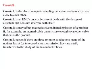
Mutual Inductance and Capacitance • Crosstalk is the coupling of energy from one line to another via: • Mutual capacitance (electric field) • Mutual inductance (magnetic field) Mutual Inductance, Lm Mutual Capacitance, Cm Zo Zo Zo Zo far far Cm Lm near Zs near Zs Zo Zo Crosstalk Overview
Mutual Inductance and Capacitance “Mechanism of coupling” • The circuit element that represents this transfer of energy are the following familiar equations • The mutual inductance will induce current on the victim line opposite of the driving current (Lenz’s Law) • The mutual capacitance will pass current through the mutual capacitance that flows in both directions on the victim line Crosstalk Overview
Crosstalk Induced Noise“Coupled Currents” • The near and far end victim line currents sum to produce the near and the far end crosstalk noise Zo Zo Zo Zo far far ICm ILm Lm near near Zs Zs Zo Zo Crosstalk Overview
Crosstalk Induced Noise“Voltage Profile of Coupled Noise” • Near end crosstalk is always positive • Currents from Lm and Cm always add and flow into the node • For PCB’s, the far end crosstalk is “usually” negative • Current due to Lm larger than current due to Cm • Note that far and crosstalk can be positive Zo Zo Far End Driven Line Un-driven Line “victim” Zs Near End Driver Zo Crosstalk Overview
Time = 0 Near end crosstalk pulse at T=0 (Inear) ~Tr V Near end crosstalk Zo TD Far end crosstalk pulse at T=0 (Ifar) ~Tr Time= 1/2 TD 2TD V Zo far end crosstalk Zo Time= TD Far end of current terminated at T=TD V Zo Zo Time = 2TD Near end current terminated at T=2TD V Zo Zo Graphical Explanation Crosstalk Overview
Zo Zo Far End Driven Line Un-driven Line “victim” Zs Near End Driver Zo Crosstalk Equations TD Terminated Victim A B Tr ~Tr Tr TD 2TD Far End Open Victim Zo Far End Driven Line Un-driven Line “victim” A B C Zs Near End Driver ~Tr Zo ~Tr Tr Crosstalk Overview 2TD
Crosstalk Equations TD Near End Open Victim Zo Zo Far End C A Driven Line B Un-driven Line “victim” Tr Tr Tr Zs Near End 2TD Driver 3TD • The Crosstalk noise characteristics are dependent on the termination of the victim line Crosstalk Overview
Creating a Crosstalk Model“Equivalent Circuit” • The circuit must be distributed into N segments as shown in chapter 2 C12 Line 2 Line 1 C1G C2G L11(N) L11(2) L11(1) Line 1 C1G(1) C1G(N) C1G(2) K1 K1 K1 C12(n) C12(2) C12(1) Line 2 L22(N) L22(2) L22(1) C2G(1) C2G(N) C2G(2) Crosstalk Overview
Creating a Crosstalk Model“Transmission Line Matrices” • The transmission line Matrices are used to represent the electrical characteristics • The Inductance matrix is shown, where: • LNN = the self inductance of line N per unit length • LMN = the mutual inductance between line M and N Inductance Matrix = Crosstalk Overview
Creating a Crosstalk Model“Transmission Line Matrices” • The Capacitance matrix is shown, where: • CNN = the self capacitance of line N per unit length where: • CNG = The capacitance between line N and ground • CMN = Mutual capacitance between lines M and N Capacitance Matrix = • For example, for the 2 line circuit shown earlier: Crosstalk Overview
Example Calculate near and far end crosstalk-induced noise magnitudes and sketch the waveforms of circuit shown below: Vsource=2V, (Vinput = 1.0V), Trise = 100ps. Length of line is 2 inches. Assume all terminations are 70 Ohms. Assume the following capacitance and inductance matrix: L / inch = C / inch = The characteristic impedance is: Therefore the system has matched termination. The crosstalk noise magnitudes can be calculated as follows: v R1 R2 Crosstalk Overview
200mV/div 100ps/div Example (cont.) Near end crosstalk voltage amplitude (from slide 12): Far end crosstalk voltage amplitude (slide 12): The propagation delay of the 2 inch line is: Thus, Crosstalk Overview
Effect of Crosstalk on Transmission line Parameters • Key Topics: • Odd and Even Mode Characteristics • Microstrip vs. Stripline • Modal Termination Techniques • Modal Impedance’s for more than 2 lines • Effect Switching Patterns • Single Line Equivalent Model (SLEM) Crosstalk Overview
Even Mode Odd Mode Odd and Even Transmission Modes • Electromagnetic Fields between two driven coupled lines will interact with each other • These interactions will effect the impedance and delay of the transmission line • A 2-conductor system will have 2 propagation modes • Even Mode (Both lines driven in phase) • Odd Mode (Lines driven 180o out of phase) • The interaction of the fields will cause the system electrical characteristics to be directly dependent on patterns Crosstalk Overview
Odd Mode Transmission +1 -1 Electric Field: Odd mode Magnetic Field: Odd mode • Potential difference between the conductors lead to an increase of the effective Capacitance equal to the mutual capacitance +1 -1 • Because currents are flowing in opposite directions, the total inductance is reduced by the mutual inductance (Lm) V Drive (I) I Induced (-ILm) Lm Induced (ILm) Drive (-I) -I Crosstalk Overview
Odd Mode Transmission“Derivation of Odd Mode Inductance” L11 I1 Mutual Inductance: Consider the circuit: + V1 - I2 + V2 - L22 Since the signals for odd-mode switching are always opposite, I1 = -I2 and V1 = -V2, so that: Thus, since LO= L11 = L22, Meaning that the equivalent inductance seen in an odd-mode environment is reduced by the mutual inductance. Crosstalk Overview
Odd Mode Transmission“Derivation of Odd Mode Capacitance” V2 Mutual Capacitance: Consider the circuit: C1g Cm V2 C1g = C2g= CO = C11– C12 C2g So, And again, I1 = -I2 and V1 = -V2, so that: Thus, Meaning that the equivalent capacitance for odd mode switching increases. Crosstalk Overview
Odd Mode Transmission“Odd Mode Transmission Characteristics” Impedance: Thus the impedance for odd mode behavior is: Explain why. Propagation Delay: and the propagation delay for odd mode behavior is: Crosstalk Overview
Even Mode Transmission Electric Field: Even mode +1 +1 +1 +1 Magnetic Field: Even mode • Since the conductors are always at a equal potential, the effective capacitance is reduced by the mutual capacitance • Because currents are flowing in the same direction, the total inductance is increased by the mutual inductance (Lm) V Drive (I) I Induced (ILm) Lm Induced (ILm) Drive (I) I Crosstalk Overview
Even Mode TransmissionDerivation of even Mode Effective Inductance L11 Mutual Inductance: Again, consider the circuit: I1 + V1 - I2 + V2 - L22 Since the signals for even-mode switching are always equal and in the same direction so that I1 = I2 and V1 = V2, so that: Thus, Meaning that the equivalent inductance of even mode behavior increases by the mutual inductance. Crosstalk Overview
Even Mode TransmissionDerivation of even Mode Effective Capacitance V2 Mutual Capacitance: Again, consider the circuit: C1g Cm V2 C2g Thus, Meaning that the equivalent capacitance during even mode behavior decreases. Crosstalk Overview
Even Mode Transmission“Even Mode Transmission Characteristics” Impedance: Thus the impedance for even mode behavior is: Propagation Delay: and the propagation delay for even mode behavior is: Crosstalk Overview
Odd and Even Mode Comparison for Coupled Microstrips Even mode (as seen on line 1) Input waveforms Impedance difference V1 Odd mode (Line 1) Probe point Line 1 Line2 v1 v2 V2 Delay difference due to modal velocity differences Crosstalk Overview
Microstrip vs. Stripline CrosstalkCrosstalk Induced Velocity Changes • Chapter 2 defined propagation delay as • Chapter 2 also defined an effective dielectric constant that is used to calculate the delay for a microstrip that accounted for a portion of the fields fringing through the air and a portion through the PCB material • This shows that the propagation delay is dependent on the effective dielectric constant • In a pure dielectric (homogeneous), fields will not fringe through the air, subsequently, the delay is dependent on the dielectric constant of the material Crosstalk Overview
Microstrip vs. Stripline CrosstalkCrosstalk Induced Velocity Changes • Odd and Even mode electric fields in a microstrip will have different percentages of the total field fringing through the air which will change the effective Er • Leads to velocity variations between even and odd Microstrip E field patterns +1 -1 +1 +1 Er=1.0 Er=1.0 Er=4.2 Er=4.2 • The effective dielectric constant, and subsequently the propagation velocity depends on the electric field patterns Crosstalk Overview
+1 -1 +1 +1 Er=4.2 Er=4.2 Microstrip vs. Stripline CrosstalkCrosstalk Induced Velocity Changes • If the dielectric is homogeneous (I.e., buried microstrip or stripline) , the effective dielectric constant will not change because the electric fields will never fringe through air Stripline E field patterns • Subsequently, if the transmission line is implemented in a homogeneous dielectric, the velocity must stay constant between even and odd mode patterns Crosstalk Overview
Microstrip vs. Stripline CrosstalkCrosstalk Induced Noise • The constant velocity in a homogeneous media (such as a stripline) forces far end crosstalk noise to be zero • Since far end crosstalk takes the following form: • Far end crosstalk is zero for a homogeneous Er Crosstalk Overview
+1 R1 Odd Mode Equivalent -1 R2 R1 R3 Virtual Ground in center R2 2R3 +1 Even Mode Equivalent R1 -1 +1 2R3 R2 Termination TechniquesPi and T networks • Single resistor terminations described in chapter 2 do not work for coupled lines • 3 resistor networks can be designed to terminate both odd and even modes T Termination Crosstalk Overview
Termination TechniquesPi and T networks • The alternative is a PI termination PI Termination R1 R1 +1 ½ R3 Odd Mode Equivalent R3 -1 ½ R3 R2 R2 -1 +1 R1 Even Mode Equivalent +1 R2 Crosstalk Overview