Download
1 / 28
330 likes | 636 Vues
Specific Industrial Waste – Refining Industry. Objectives. Introduction Characteristics of Petroleum Refining Products Petroleum Refining Process Wastes From Refinery Processes Refinery Air Emissions Control Refinery Solid Waste Treatment Refinery Waste Water Treatment. Introduction.

E N D
Specific Industrial Waste – Refining Industry
Objectives • Introduction • Characteristics of Petroleum Refining Products • Petroleum Refining Process • Wastes From Refinery Processes • Refinery Air Emissions Control • Refinery Solid Waste Treatment • Refinery Waste Water Treatment
Introduction • What is Refining? Purification of substance • Refining of the materials Solids, liquids and gases • Invention of Refineries Discovered at 1954 but developed 20th century
Petroleum Refining Process • What is petroleum oil? A complex mixture containing thousands of different organic hydrocarbon molecules such as, – 83-87% Carbon – 11-15% Hydrogen – 1-6% Sulfur • Paraffins – saturated chains • Naphthenes – saturated rings • Aromatics – unsaturated rings • This natural petroleum oil can be refined into various useful products via, (a) Separation (b) Conversion (c) Finishing
Petroleum Refining Processes • Separation Processes • Atmospheric distillation • Vacuumn distillation • Conversion Processes • (a) Fluid Catalytic Cracking • (b) Thermal and Catalytic Cracking • (c) Hydrocracking • (d) Hydrotreating • (e) Catalytic Reforming • (f) Isomerization • (g) Alkylation • Finishing Processes • Purification – to remove impurities from the product
Conversion Processes • Fluid Catalytic Cracking • - To convert low value gas oils to valuable products (naphtha and diesel) and slurry oil. • - Includes catalytic and thermal cracking (heavy fractions to lighter) • Thermal Cracking Catalytic Cracking • Free radical mechanism Carbenium ion mechanism • Lower octane number (less branched HC) High octane number • No true equilibrium is achieved Equilibrium is attained • So, catalytic cracking is preferred
Catalytic Cracking Mechanisms • Relative order of cracking of the various hydrocarbon types over a silica-alumina catalysts is, • olefins > alkyl aromatics > naphthenes > paraffins > polynuclear aromatics
Hydrocracking • In the presence of an elevated partial pressure of hydrogen. • Used to remove feed contaminants (N, S, metals) and to convert low value gas oils to valuable products (naphtha, middle distillates) • Favourable catalysts - Ni-W (used when sulfide and other poisons are high) supported on amorphous silica-alumina or a noble metal like Pt or Pd (to get gasoline as a desired product) supported on highly active Zeolite materials.
Hydrotreating • To remove contaminants (sulfur, nitrogen, metals) and saturate olefins and aromatics to produce a clean product for further processing or finished product sales. • To desulfurize naphtha prior to reforming, reduce the sulfur and aromatic contents of kerosene and diesel. • Catalysts are Co-Mo (preferred for hydrodesulfurization) or Ni-Mo (preferred for hydrodenitrogenation) sulfides supported on alumina
Catalytic Reforming • To convert low-octane naphtha into a high-octane reformate for gasoline blending and/or to provide aromatics (benzene, toluene, and xylene) for petrochemical plants. • Desired reactions include: • dehydrogenation of naphthenes to form aromatics; • isomerization of naphthenes; • dehydrocyclization of paraffins to form aromatics; and • isomerization of paraffins
Isomerization & Alkylation • Isomerization of light naphtha (C5-C7) into high octane gasoline blend stock (isomerate) • Catalysts generally mordenite and ZSM-5 • Alkylation of butenes with isobutene to isooctane • Catalysts generally anhydrous HF or conc. H2SO4, (environmentally undesirable) • So, liquid acid catalysts are replaced by solid acid catalysts such as Zeolite
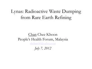
Wastes From Refinery Processes • Refinery wastes are mostly divided into three types are, • Air emissions • CO, NOx, SOx, hydrocarbons, fugitive emissions (hydrocarbons, H2S, NH3) • Residual wastes or solid waste • Spent catalysts (metals from crude oil and hydrocarbons), spent catalysts fines (Aluminum silicate and metals), API separator sludge (phenols, metals, and oil), • Chemical precipitation sludge (chemical coagulants, oil), DAF floats, biological sludge, metals, oil, suspended solids, spent lime. • Wastewater • All the major processes produce waste waters (hydrocarbons, hydrogen sulfide, ammonia, organic sulfur compounds, organic acids, and phenol).
Wastes From Refinery Processes Emissions and waste generation in approximate quantities
Waste Treatment (Air emission control) Selective-Catalytic Reduction of NOx The main principle is the reaction of ammonia with NO in excess O2 over Pt catalysts. 4NH3 + 4NO + O2 → 4N2 + 6H2O 4NH3 + 4NO2 + O2 → 3N2 + 6H2O Non-Selective Catalytic Reduction of NOx This process is for the removal of NOx (mostly NO2) from the tail gas of nitric acid plants. Since the tail gas has some free O2, this is removed by injection of CH4 or LPG. The NO2 is then reduced by further addition of HC or the byproducts. HC + NO2 → NO + CO2 + H2O HC, CO, H2 + NO → N2 + CO2 + H2O
Waste Treatment (Air emission control) Prevention of SOx emission This can be controlled through the addition of promoters to the catalysts, such as MgO, Rare earth oxides and V oxides which prevents their release into the atmosphere byreacting them in the regenerator. Other additives also added to improve the CO combustion and SO2 oxidation are Pt or Pd on silica-alumina or alumina. The functioning of these additives are, Regenerator : S in coke + O2 → SO2 (> 90%) + SO3 (< 10%) SO2 + ½ O2 → SO3 (additive used) MO + SO3 → MSO4 Reactor : MSO4 + 4H2 → MS + 4H2O and/or MSO4 + 4H2 → MO + H2S + 3H2O Stripper : MS + H2O → MO + H2S
Solid Waste Treatment • Some common techniques for catalysts disposal or treatment such as, • Use long life catalysts and regeneration to extend the catalyst life cycle; • Use appropriate on-site storage and handling methods, (e.g.,submerging • pyrophoric spent catalysts in water during temporary storage and transport until • they can reach the final point of treatment to avoid uncontrolled exothermic • reactions); • Return spent catalysts to the manufacturer for regeneration or recovery, • or transport to other off-site management companies for handling, heavy or • precious metals recovery/ recycling, • Overcoming Catalytic poisoning • Involves strong interaction between a component of the feed or products and • the active sites of the catalyst. • Use of an additive which preferably adsorbs the poison. • So, choosing of catalysts is resonably facile (to remove poison).
Solid Waste Treatment Component Recovery The most common approach is to recover totally metals in the catalyst. This is done by a combination of roasting and leaching. Catalyst is first ground and roasted at 600°C to produce metal oxides and to remove coke. A second roast at 750°C in the presence of sodium carbonate produces soluble salts: V2O5 + Na2CO3 → 2NaVO3 + CO2 MoO3 + Na2CO3 → NaMoO4 + CO2 Leaching with water at 100°C is then followed by treatment with ammonium chloride or calcium chloride: NaVO3 + NH4Cl → NH4VO3 ↓ + NaCl 2NH4VO3→ V2O5 + 2NH3 + H2O NaMoO4 + CaCl2 → CaMoO4 + 2NaCl 500°C
Waste Water Treatment • Typical wastewater treatment steps include: • grease traps, skimmers, dissolved air floatation or oil water separators for • separation of oils and floatable solids; • filtration for separation of filterable solids; • flow and load equalization; • sedimentation for suspended solids reduction using clarifiers; • biological aerobic treatment, for reduction of soluble organic matter (BOD); • chemical or biological nutrient removal for reduction in nitrogen and phosphorus; • chlorination of effluent when disinfection is required; • dewatering and disposal of residuals in designated hazardous waste landfills
Waste Water Treatment Waste water storage tanks and systems in Refinery
Waste Water Treatment • Additional engineering controls may be required for water water treatment • containment and treatment of volatile organics stripped from various unit • operations in the wastewater treatment system, • advanced metals removal using membrane filtration or other physical/ • chemical treatment technologies, • (iii) removal of recalcitrant organics and non biodegradable COD using activated • carbon or advanced chemical oxidation, • (iv) reduction in effluent toxicity using appropriate technology (such as reverse • osmosis, ion exchange, activated carbon, etc.), and • (v) containment and neutralization of nuisance odors.
Biological Waste Water Treatment Some refineries have lagoons or final polishing ponds Aerobic bacteria convert wastes into CO2, NH3, and phosphates, which, in turn, are used by the algae as food. Anaerobic bacteria convert substances in wastewater to gases, such as H2S, NH3, and CH3OH. Many of these by products are then used as food by both aerobic bacteria and algae in the layers above.
Waste Water Treatment The treated water should have the maximum limits of the following, BOD (Biological Oxygen Demand) 25 mg/l (30 day average) 45 mg/l (7 day average) TSS (Total Suspended Solids) 30 mg/l (30 day average) 45 mg/l (7 day average) pH shall remain between 6.0 and 9.0 In addition, there shall be no visible solids and/or visible oil or greases in the discharge.