Download
1 / 14
140 likes | 239 Vues
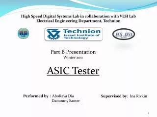
Characterization Presentation Spring 2010 ASIC Tester Abo -Raya Dia - 4 th year student Damouny Samer - 4 th year student. Supervised by: Ina Rivkin. Overview :. Objective: testing the ASIC’s functional correctness

E N D
Characterization Presentation Spring 2010 ASIC Tester Abo-Raya Dia- 4th year student DamounySamer- 4th year student Supervised by: Ina Rivkin
Overview : • Objective: testing the ASIC’s functional correctness • Comparing the provider’s input with the expected outputs • Providing options for viewing and analyzing the results
PC User Interface FPGA Project Description : ASIC tester DUT PCIe NOGA StarII Adaptive board GiDELPROCe
Technical specifications : • The tester supports up to 96 inputs/outputs and up to • 48 bi-directional pins. • Samples I/O signals up to 100 MHz rate. • Independent voltage suppliers: -10 v- 10v. • 1G memory for each input and output vectors . • Two clk pins .
Hardware: • Sending the vectors from DDR A to FIFO IN (working with the high Freq. ) • Transferring the vectors to the DUT via the voltage translators on the PSDB • (working with the DUT Freq. ) • Sampling the DUT outputs and saving them in DDR B
Software: • Configuring the ports • Defining the ASIC’s work conditions (clocks & voltage level ) • Sending the input vectors to the DDR • Comparing the outputs with the expected outputs . Configuration mode screen Debug mode screen
Hardware Changes : The Loop command : Send the vectors between lines a & b N times . Requirements: Loop nesting :2. Writing the output vectors to the output file in a cyclic way. The need to match between the inputs & outputs .
2. Embedded Logic Analyzer : Allow the user to see the signals between the FPGA & the DUT, when a trigger occured. Requirements : a. In order to see the signals , the User should launch Altera Signal Tap , with no need to compile the design . b. To raise the trigger when we recognize a combination of the input Data .
Software Changes : 3. Waves Library: Creating an input vectors based on waves library , e.g. : counter (increment/decrement), pulse, random , const. value ,compound clk (clk edges time ,frequency , Duty cycle ) . Counter : start from a , each clock cycle increment or decrement the vector by x , till you reach b .
4. Sampling frequency: Allow the user to sample the outputs with a higher frequency than the DUT. 5. Graph : A graph for all the output files, when each file was with another frequency .
Summary: The new debug mode Logic Analyzer Loop Load wave Sampling Freq. Summary Graph