Download

1 / 61
610 likes | 741 Vues
MICE – MUON Interface meeting at Mission Inn, Riverside, California January 27 - 30, 2004. MICE Cooling Channel Integration Issues. Wing Lau – Oxford & Steve Virostek -- LBL. Outline of this discussion:.

E N D
MICE – MUON Interface meeting at Mission Inn, Riverside, California January 27 - 30, 2004 MICE Cooling Channel Integration Issues Wing Lau– Oxford & Steve Virostek-- LBL
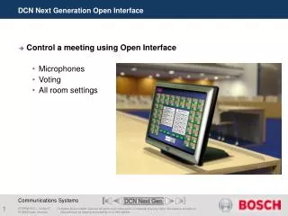
Outline of this discussion: Agreement of scope of supply and extent of interface among different suppliers of the same module. Distinguishing between a stand-alone item and an interface item through drawing convention Using the global reference point as an interface check. This is introduced to the collaboration as the “coat hanger” technique.
Agreement of scope of supply and extent of interface among different suppliers of the same module. • NIU / IIT will supply the following:- • The Absorber windows, the Safety windows;the Large end plates. • It should provide the following interface information to:- • the Absorber Body supplier:- • Absorber Window and flange dimensionOthers? • the Focus Coil Module supplier:- • PCD, size and number of the threaded holes for the Safety Window and the Large End FlangeSurface finish at the seated area of the mechanical sealOthers?
KEK will supply the follow:- • Absorber Body; • Liquid Hydrogen and Gas Helium feed pipes to and out of the Absorber body to the Focus Coil Vacuum Vessel inlet entrance nozzle;Anchoring arrangement for the Absorber body; • LH2 Spillage bucket; • As a minimum, it should provide the following information to:- • The Window supplier:- • PCD, size and number of holes for the Absorber Window attachment • Surface finish at the seat area of the mechanical seal; • Mechanical seal and bolting requirement to guarantee leak-tightness; • Window flange geometry required to allow the routing and attachment of the LH2 and GHe feed pipes; • Others? • The Focus Coil supplier:- • Anchoring details for Absorber body and the LH2 spillage bucket; • Any fixing arrangement for the LH2 and GHe feed pipes; • Sealing arrangement between the feed inlet pipes and the entrance nozzle to the top of the Warm Vessel. • Others?
Oxford / RAL will supply the follow:- • Rest of the items in the Focus Coil Modules except those already in the KEK and NIU/IIT’s scope of supply; • Support structure for the Focus Coil Modules • As a minimum, it should provide the following information to:- • The Window supplier:- • Space envelope and dimension of the Focus Coil Warm bore tube and its Safety Window attachment ring; • Space envelop and dimension of the Large End Flange attachment ring; • Others? • The Absorber supplier:- • Space envelope and dimension of the Focus Coil Warm bore tube; • Space envelope and dimension of the Large End Flange attachment ring; • Space envelop for the LH2 & GHe feed pipes between the Large End Flange and the Cryostat; • Size and location of the Warm Vessel top entrance nozzle; • Space envelop for the LH2 spillage bucket; • Any fixing constraint for the LH2 and GHe feed pipes; • Others? • The Coupling Coil and Detector Module suppliers • Solution on the connection between modules • Common agreement on the structural support design for the modules • Others
Definition of supply scope between Oxford/RAL, NIU/IIT and KEK Colour code:- Oxford / RAL supply is in black; KEK supply is in blue; NIU / IIT supply is in red Pink indicates interface areas
Supply Package B (KEK)1 Off Absorber Body with radial supports / spacersAbsorber Axial anchoring bracketsLH2 & GHe Feeds including transition joints & pipe flange connections1 off MLI Spillage bucket Supply Package A (NIU/IIT):-2 off Absorber Windows with flanges2 off Safety Windows with flanges1 off Large End Flange Principal package supply (Oxford / RAL)All the items within the Focus Coil Module except those which are already in the supply of Packages A & B
Distinguishing between a stand-alone item and an interfacing item through drawing convention Stand alone items are those within the scope and responsibility of the same supplier and as such it does not interface with any other equipment suppliers. As an example, the Magnet Coil is a stand alone item as its design bears no impact on either the Window or the Absorber supplier. Where items made by one supplier and joined to those made by another supplier, they are known as interfacing items. As an example, the flange in the Large End Plate (marked in Pink) is an interface item as it interfaces with the Warm Vessel supplier. In the drawing on the left, there are three different suppliers, each is marked with a different colour code. The parts that interface with other parts of different suppliers are marked in pink. Drawings on the Pink parts have a joined ownership of all the interfacing suppliers. In the MICE project, the pink parts will have a different drawing convention than the rest. Any changes made on these drawings will be notified to all the related interface suppliers for comments and consent.
With Focus Coil Module supplier, i.e. Oxford / RAL With Absorber supplier, i.e. KEK With Window supplier, i.e. NIU / IIT With Coupling Coil and / or Detector module suppliers Parts marked in Pink colour are interface parts Interface Colour Codes
The Coat Hanger technique An equipment which has multiple suppliers would comprise stand alone parts and interface parts as explained previously. The design and supply of the stand alone parts are the sole responsibility of the individual suppliers, but the design and arrangement on the interface parts have the joint ownership of all those who have an interest in that interface. The WBS project engineer is responsible for specifying the interface dimensions and space envelop. As long as the stand alone equipments are within the given space envelop, the suppliers are free to make changes to them. No approval is needed for making these changes. But any alteration to the interface parts must have the approval of the project engineer. This must be communicated via the interface drawings. Even then, it is still not possible to catch all the changes made to the interface drawings because of the nature and the size of the project. A better system which could automatically trigger a warning to the project engineer of changes made is therefore needed. The Coat Hanger technique is designed to offer this facility and is a good way to ensure interface compatibility
The Coat Hanger technique (continue) The conventional way of assembling the different parts together is by attaching the adjoining parts to a common interface boundary. Where there are multiple interfaces, or where one part joins onto another part and another part and so forth, it would be difficult to define the order of interface. It would also accumulate errors as parts are assembles related to each other only locally and not globally. This makes the checking of interface compatibility extremely difficult. As an example, the tiling of a wall……….
This is what the drawing says how the wall should be tiled This tile is slightly oversized, but not noticeable without a dimensional check Sequence of tiling is as shown:Black arrows first, followed by red arrows The Coat Hanger technique (continue) These are the supplied tiles
The Coat Hanger technique (continue) Mismatch / foul went undetected until the job is nearly finished
The Coat Hanger technique (continue) The conventional way of assembling the different parts together is by attaching the adjoining parts to a common interface boundary. Where there are multiple interfaces, or where one part joins onto another part and another part and so forth, it would be difficult to define the order of interface. It would also accumulate errors as parts are assembles related to each other only locally and not globally. This makes the checking of interface compatibility extremely difficult. The way to overcome this is to avoid having to assemble parts onto each other. In this new concept, every parts will have a reference centre which coincides with one of the globally registered centres designed to position the magnet modules relatively to the beam line and then to the experimental hall. This reference centre acts like a coat hanger
Global reference centre The Coat Hanger technique (continue)
Global reference centre The Coat Hanger technique (continue) Reference centre for the individual tile
Global reference centre The Coat Hanger technique (continue)
The Coat Hanger technique (continue) Global reference centre Reference centre for the individual tile
The Coat Hanger technique (continue) Global reference centre Reference centre for the individual tile
Global reference centre The Coat Hanger technique (continue)
Global reference centre The Coat Hanger technique (continue)
Global reference centre Overlap / mismatch identified The Coat Hanger technique (continue)
Global reference centre The Coat Hanger technique (continue)
The Coat Hanger technique (continue) The conventional way of assembling the different parts together is by attaching the adjoining parts to a common interface boundary. Where there are multiple interfaces, or where one part joins onto another part and another part and so forth, it would be difficult to define the order of interface. It would also accumulate errors as parts are assembles related to each other only locally and not globally. This makes the checking of interface compatibility extremely difficult. The way to overcome this is to avoid having to assemble parts onto each other. In this new concept, every parts will have a reference centre which coincides with one of the globally registered centres designed to position the magnet modules relatively to the beam line and then to the experimental hall. This reference centre acts like a coat hanger The referencing system works like a global navigation system. Through the reference centres, we can refer the position of each parts to a global coordinate. By hanging the various parts to a globally registered centre, it will automatically assemble the parts to a pre-defined position. Any interface incompatibility will be easily detected as each equipment / parts will have its unique place in the global coordinate system. No two parts should have the same coordinates. We will insist on this centre being retained on all the stand alone and interface drawings.
This is how it works on MICE: There are different levels of reference centre, designated to have a similar “level” allocation as the WB packages. The level 1 reference centre is the centre of the experimental hall; The level 2 reference centres are those along the beam line centre for the positioning of each of the modules; The level 3 reference centres are the centres of the individual modules As an example:- The Focus Coil module will have a level 3 reference centre. All the parts associated with the windows and the absorber will be referenced to this level 3 reference centre. The Focus Coil modules, the Coupling Coil, the detector modules and any equipment that are aligned to the beam centre line will be referenced to the level 2 reference centre. The beam line centres will be referenced to the level 1 reference centre etc.
These parts will have level 3 reference centre attached The level 3 reference centre on the FC module
All the AFC parts will then be hung to the level 3 reference centre at the Focus Coil