Download
1 / 26
260 likes | 388 Vues
TITAC: Design of a QDI microprocessor. TITAC: Tokyo Institute of Technology TITAC-1: IEEE Design & Test (Summer 94) 1. main goal: explore the design methodology 2. 8-bit Von Neumann microprocessor is designed TITAC-2: ICCD’97 32-bit fully functional

E N D
TITAC: Design of a QDI microprocessor • TITAC: Tokyo Institute of Technology • TITAC-1: IEEE Design & Test (Summer 94) • 1. main goal: explore the design methodology • 2. 8-bit Von Neumann microprocessor is designed • TITAC-2: ICCD’97 32-bit fully functional • microprocessor based on MIPS 2000 Reading 6
Outline • Goal of TITAC-1 • Organization and Instruction sets • Design methodology • 1. control path • 2. data path
Goal of TITAC-1 • Not to design a fully functional microprocessor • but to explore the design methodology • A. determine suitable specification • B. Implementation. • Establish a library of building blocks for design • automation of Async. VLSI systems.
Organization of TITAC • TITAC is an 8-bit Von Neumann microprocessor • Single-accumulator architecture • TITAC consists of • * Control section: • 1. controls data flow of datapath section • 2. two controllers: hardwired and • microprogrammed • A. selectable by an external switch. • B. designed by two authors independently. • * Datapath section:
Organization of TITAC • Datapath section: • 1. An ALU (Arithmetic Logic Unit). • 2. Instruction Register (IR) • 3. One Accumulator (Acc) • 4. Program Counter (PC) • 5. Memory Address Register (MAR) • 6. Input Buffer (In) • 7. Output Buffer (Out) • 8. Memory Interface (to Main Memory) • See Fig 1(TITAC organization) in pp. 53
Instruction Set of TITAC • Memory Reference Instructions: (two Bytes) • A. opcode + operand • B. address modes: • 1. Immediate • 2. Stack pointer relative • 3. Indirect • 4. Direct • C. ADD mem ==> Acc := mem + Acc • ADC mem: add with carry ... • Branch Instructions: (two bytes) • Miscellaneous Instructions: (one byte)
Protocol of TITAC • Two phase, event-driven scheme: • ( i.e. four-phase handshaking or return to zero) • A: working phase: 1: working transient • 2: working stable • B: idle phase: 3: idle transient • 4: idle stable
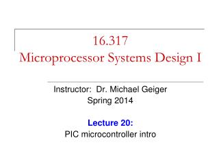
Specification: Data dependency graph • High Performance ==> • Execute as many micro-operations as possible. • Need to analyze dependency relations: • Use dependency graph to analyze micro-operations. • Five types of primitive elements: (see Fig 3) • A. micro-operations: register to register data transfer • B. fork: parallel execution threads • C. join: synchronization of parallel execution • D. select: condition branch. • E. merge: merge signals. • Example: DDG of jmp instruction (Fig 4).
Data dependency graph: Jump Write After Read Write After Write
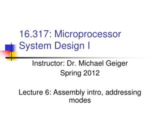
Implementation: dependency graph • Five types of primitive elements: (see Fig 3) • A. micro-operations: Q-element (read + write). • B. fork: fan-out wires • C. join: Muller’s C element • D. select: decoder (one out of n code) • E. merge: EX-OR • Example: Fig 5.
Jump: Jump: Control path Data path
Q-element • Inputs: Ui, Li Outputs: Lo, Uo • 2 AND + 2 Inv + a C-element • How it work? Ui Lo Li Uo
Performance Issue • Performance problems: • Need to reset (idle phase) the circuit. • Solution: data analysis + Auto Sweeping Module
Auto Sweeping Module (ASM) • Improve the latency. • Uo+ ==> start next computation • ==> reset current computation • Parallel execution of working phase and idle phase Ui Lo Li Uo
Auto Sweeping Module (ASM) • Replacement Q-element with ASM: • A. replace each Q-element with one ASM. • B. Analyze data dependency: • WAW and WAR • C. add AND gates to ensure the dependency.
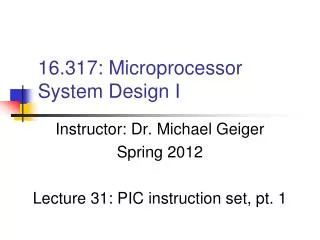
DDG ASM JUMP
Q JUMP ASM JUMP
Data Path Design • Binary Decision Diagram (BDD) to implement combination logic such as ALU functions • For example:
Data Path Design • Binary Decision Diagram (BDD) to implement combination logic such as ALU functions • For example:
Multiport Register • Two port register: