Download
1 / 19
190 likes | 327 Vues
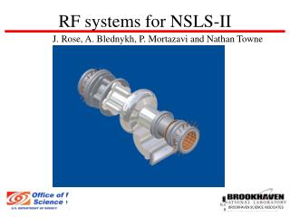
Accelerator Laboratory. RF-Systems for STF S. Fukuda. Content Introduction Status of STF and Plan forFY2006 LLRF Summary. Accelerator Laboratory. C. r. y. o. g. e. n. i. c. s. C. M. (. 3. 5. M. V. /. m. ). 5. M. W. 1. 0. M. W. F. o. r. 5. M. W. F. o.

E N D
Accelerator Laboratory RF-Systems for STF S. Fukuda Content Introduction Status of STF and Plan forFY2006 LLRF Summary S. FUKUDA LCPAC 060325
Accelerator Laboratory C r y o g e n i c s C M ( 3 5 M V / m ) 5 M W 1 0 M W F o r 5 M W F o r 1 0 M W S. FUKUDA LCPAC 060325
Plan to Phase-1 (for 2 years) Accelerator Laboratory • For #1-Modulator: Reinforce the modulator with bouncer circuit using the PNC modulators and1:6 pulse-transformer making use of JHP pulse-transformer. Old IGBT is reused. PLC Control system is newly equipped. Almost done • For #2 modulator: New modulator which is capable to drive 10 MW MBK klystron is designed and manufactured. This is based on the TESLA Design. New device IEGT is promising. Waiting the tender • Two 5-MW Klystrons will be prepared. • Thomson TH2104A (1.296GHz in KEK used in JHP) is tested at 1.3GHz. Under testing • Procurement of Thales TH2104C is under going as the replaceable klystron. Purchased • If competitive budget or equivalent is approved, a multi-beam klystron will be introduced. Planning in FY2006 • Two kinds of power distribution is tested to compare the performance and cost. under progressing • LLRF system is prepared for the beam acceleration test. under progressing S. FUKUDA LCPAC 060325
Accelerator Laboratory, KEK Specification of STF-RF S. FUKUDA LCPAC 060325
Concept of test facility for quick and inexpensive start utilizing existing properties Accelerator Laboratory Making use of power supply and waveguide component moved from PNC (Power Reactor and Nuclear Fuel Corp). Power supply has 3 modes; (1)Short pulse (100ms), (2)long pulse (4ms) and (3)CW for the modulating anode type klystron. For mode(2), possible klystron is modulating anode type TH2115 (Thales). About 2MW output is possible for this case. Reform to (PT+Bouncer) allows to use TH2104A(C). Photo of Modulator in PNC Block diagram of PNC modulator 5-10MW S. FUKUDA LCPAC 060325
Accelerator Laboratory Modulator Development Install of Pulse transformer Waveform of modulator without bouncer • Modulator reformation was almost done and started operation for coupler test. • Reformation was performed as half the price as the newly built modulator. • Bouncer circuit will be added in middle of April in 2006. S. FUKUDA LCPAC 060325
Accelerator Laboratory Candidate Klystrons(1.3GHz、LongPulse) 10 MWPeak 10 MWPeak 5-10 MW S. FUKUDA LCPAC 060325
Accelerator Laboratory Klystron test status (1)Performance of the klystron, which was bought 15 years ago, was checked in short pulse operation(3micro sec pulse width) Applied voltage (kV) Waveform: voltage (top), Current (bottom) S. FUKUDA LCPAC 060325
Accelerator Laboratory Klystron Test-Photo of test station and long pulse test High Power Circulator Klystron Pulse Transformer Tank RF Window IGBT Sw Cabinet Variable Shorted WG High power Water Load Coupler Insertion Points RF waveform measured in 060301 S. FUKUDA LCPAC 060325
Accelerator Laboratory Modulator and klystron plan in FY2006 • Modulator New modulator (#2) based on the ILC-BCD type will be manufactured. Preparation of the tender is under going. Full completion depends on budget. • Klystron • Second TH2104C (5MW tube) will be conditioned for the waveguide components’ evaluation or RF gun test. • Collaboration of the 10MW-MBK, especially of the horizontally mounted MBK , with Toshiba Corp. is considered. It is also depends on the budget. • Design work of the 10 MW-MBK with the 36 beam-lets which is operated in 50 kV are planed. Collaboration between KEK and Russian engineers is under going. S. FUKUDA LCPAC 060325
Coupler test configuration Accelerator Laboratory Durability test under the large reflection power. High-power circulator is required to protect the klystron Usual test terminated by a high power load Coupler developed by Kako etc. Waveguide Layout and coupler test S. FUKUDA LCPAC 060325
Phase-1 Cavity Test WG Configuration Accelerator Laboratory Another type of PDS, which is possible to change the phase and Qext of the cavities independently, should be also studied. At first, 8 circulators will be used to have an initial test. S. FUKUDA LCPAC 060325
Accelerator Laboratory LLRF system @STF Phase1 Power meter Fast Interlock Arc sensor Klystron linerlizer 400 W Amp. Digital FB cPCI system will be installed in Aug.2006 J-PARC based LLRF system Digital FB system using a FPGA board LLRF PLC system control digital FB system S. FUKUDA LCPAC 060325
Accelerator Laboratory JPARC linac LLRF 4x14bit ADCs 324 MHz Max. 2 cav. IF=12 MHz LO=312 MHz Sampling=48 MHz STF phase-1 10x16bit ADCs 1300 MHz Max. 8 cav. (rocketIO) IF=10 MHz LO=1310 MHz Sampling=40 MHz STF phase-2 1300 MHz Max. 36 cav. IF=10 MHz LO=1310 MHz Sampling=40 MHz Digital cavity simulator Digital LLRF FB control @STF Phase1 Achieved stability of ~+-0.1%, ~+-0.05deg. @J-PARC Amplitude:6000, phase:0deg. S. FUKUDA LCPAC 060325
Accelerator Laboratory Real time intelligent diagnostics by DSP board Output max RF off (by diagnostics in DSP) Quench etc. FPGA & DSP boards @STF Phase1 Custom FPGA board : Mezzanine card of the commercial DSP board 10 16bit-ADCs and 2DACs + 2Rocket IO 40 MHz clock Commercial DSP board (Barcelona) (same to J-PARC system) :4x TI C6701 DSPs Can access to FPGA like an external memory of DSP 10 16bit-ADCs FPGA 2DACs S. FUKUDA LCPAC 060325
Accelerator Laboratory Software development plan for STF-Phase1 Cavity Simulator: by commercial FPGA board (Finished) FB program development (~2006.Dec) FB algorism (software development) FB operation (2006 Dec.) S. FUKUDA LCPAC 060325 Real Cavities
Accelerator Laboratory Proposal of IF mixture Now, the number of ADCs in a FPGA board is limited due to the substrate. (maybe ~15 with 16 layers in substrate) The idea is based on the ‘digital radio’ and obtaining cavity signals with a ADC. Over-sampling: IF 8 MHz & 12 MHz with 48 MHz sampling -> include averaging effect ->increase resolution Mixture of two signals decrease the resolution of analog signals but averaging increases the resolution. Cavity signals do not change during averaging (due to high Q values) →Enough IF separation S. FUKUDA LCPAC 060325
Accelerator Laboratory LLRF schedule (analog llrf and MPS) • Analog llrf (amplifier, etc.): finished • MPS: almost finished (except modification for 8 cavities) • PLC program improvement (MPS, for 8 cavities): ~ Aug.,2006 (digital FB system) • FPGA/DSP/Host program development: ~June 2006 • Brash-up of feedback algorithm by cavity simulator: July,2006-Aug.,2006 • Installation of digital FB system to STF: Aug.,2006 • Test operation at STF with cavity simulator: ~Dec. 2006 • Host/Data acquisition software development: ~Dec. 2006 S. FUKUDA LCPAC 060325
Accelerator Laboratory Summary • In FY2005, RF system for STF has been developed as planed in the beginning. • Reformation of the PNC modulator has almost done and performed the klystron test. Bouncer circuit will be installed in middle of April. • First coupler test will be scheduled in April. • Klystron bought 15 years ago was evaluated and operated normally. • Plan of the FY2006 for modulator and klystron are shown. New modulator is now under the preparation of tender. Development of MBK is also seriously considered. • LLRF is under manufactured based on the technology developed in J-PARC. • Analogue system of LLRF has installed and already operated. • Digital LLRF system are developed. Digital FB hardware for STF Phase-1 was completed and installed. • Cavity simulator and software development are scheduled in this spring to autumn. S. FUKUDA LCPAC 060325