Download
1 / 45
480 likes | 924 Vues
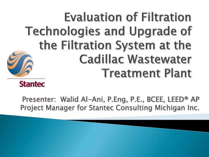
Evaluation of Filtration Technologies and Upgrade of the Filtration System at the Cadillac Wastewater Treatment Plant. Presenter: Walid Al-Ani, P.Eng , P.E., BCEE, LEED® AP Project Manager for Stantec Consulting Michigan Inc. Presentation Overview. Overview of the Cadillac WWTP

E N D
Evaluation of Filtration Technologies and Upgrade of the Filtration System at the Cadillac Wastewater Treatment Plant Presenter: Walid Al-Ani, P.Eng, P.E., BCEE, LEED® AP Project Manager for Stantec Consulting Michigan Inc.
Presentation Overview • Overview of the Cadillac WWTP • Background Information • Filtration Technologies Evaluation & Selection • Design Highlights • Construction Highlights • Post-Construction Performance • Questions and Answers
Overview of the Cadillac WWTP • Plant Rated for 3.2 MGD Average Daily Flow and 4.5 MGD Maximum Daily Flow • Influent Pump Station – Screw Pumps • Equalization Basin • Preliminary Treatment • Primary Treatment • Secondary Treatment – Activated Sludge/Chemical Addition for Phosphorous Removal • Rotating Biological Contactors • Tertiary Filters • UV Disinfection • Anaerobic Digestion • Biosolids Land Application
Background Information • Project plan prepared in 2006 to address overall plant needs – Requirement for seeking State Revolving Funds (SRF) • Tertiary Treatment major needs identified: • Replacement of the sand filters that were nearing the end of their useful life • Replacement of the sampling pumps • Replacement of the samplers • Design completed in the summer of 2007 • Construction completed in the early spring of 2008 • Overall construction cost approximately $3,800,000 • Construction cost for Tertiary Treatment Improvements approximately $1,000,000 • Construction cost for the installed filters approximately $620,000
Filtration System Before Implementing Improvements • Three sand filters (Hydroclear) commissioned in 1977 • Some rehabilitation work performed over the years including replacement of filter media, valves, and control system • Deteriorating performance and extensive backwashing necessary
Filtration Technologies Preliminary Options • Traveling Bridge Filters • Traveling Hood Filters • Disc Cloth Media Filters • Synthetic Media Filters • Deep Sand Filters • Membrane Biological Reactors (MBRs)
Traveling Bridge Sand Filters • Continuous downflows, automatic backwash, low head, granular medium depth filter. • Filter bed is divided into independent filter cells. • Treated wastewater flows through the medium by gravity and exits to the clearwell plenum via a porous-plate, polyethylene underdrain. • Each filter cell is backwashed individually by an overhead traveling – bridge assembly, while the other cells remain in service. • During the backwash cycle, wastewater is filtered continuously through the cells that are not being backwashed. • Example is the US Filter Davco Products – Gravisand.
Traveling Bridge Sand Filters Source Aqua-Aerobics Systems, Inc.
Traveling Hood Sand Filters • Similar to the Traveling Bridge Sand Filter. • Uses a pneumatically driven self – propelled hood instead of a conventional rail-mounted traveling bridge. • Simpler, more compact installation, lower equipment cost compared to the Traveling Bridge Sand Filter. • Example is EIMCO Water Technologies.
Traveling Hood Sand Filters Source Water Online
Disc Cloth Media Filters • Filter tank contains a series of circular disk elements covered with a specialized cloth media. • The cloth media traps particulates within its interior as well as forming a particulate layer upon its outer surface. • Backwash cycle begins at a predetermined water level. • During the backwash cycle, the center tube rotates while a centrifugal pump draws filtered water through a suction header from the clean side of the filter cloth. • Examples are the Aqua-Aerobic Aqua Disks and the Kruger Hydrotech Disc Filter.
Disc Cloth Media Filters Source Aqua-Aerobic Systems, Inc.
Synthetic Medium Filters • Filters use highly porous synthetic medium. • Porosity modified by compressing the filter medium. • Wastewater flows through medium; not around filtering medium as in conventional sand and anthracite filters. • Wastewater introduced in bottom of filter and flows upward through filter medium, which is retained by two porous plates. • Upper porous plate raised mechanically in backwash. Flow to filter continues and air introduced below lower porous plate causing medium to move in a rolling motion. • Example is Schreiber’s Fuzzy Filter.
Synthetic Medium Filters Source Schreiber Source: Schreiber
Deep Bed Upflow Continuous Backwash Sand Filters • Wastewater introduced into bottom of filter where it flows upward through a series of riser tubes. • Wastewater then flows upward through downward moving sand and exits filter. • Sand particles and trapped solids are drawn downward into the suction of an airlift pipe. A small volume of compressed air draws sand, solids, and water upward. • At the top of the airlift, the dirty slurry spills over into a central reject compartment. Sand settles and is cleaned further as it moves down through a washer. • Example is Parkson’sDynaSandFilter.
Deep Bed Upflow Continuous Backwash Sand Filters Source: DynaSand Source DynaSand
Membrane Biological Reactors (MBRs) • MBRs combine secondary & tertiary treatment into one process. • Integrated bioreactor uses membranes immersed in bioreactor; re-circulated MBR in which mixed liquid circulates through a membrane module located outside the bioreactor. • In the integrated bioreactor wastewater is drawn through the membranes using vacuum. Compressed air is used to scour the membrane surfaces. • In the re-circulated MBR wastewater is pumped into the membranes where solids are retained inside the membranes and wastewater passes through to the outside. The membranes are backwashed systematically to remove solids. • Examples are MBRs manufactured by Zenon, US Filter Memcor, and Envirogroup.
Membrane Biological Reactors (MBRs) Source: Memcor
Evaluation of Filtration Technologies - Performance • Required performance based on NPDES effluent limitations for the summer months listed in the Cadillac WWTP permit: • 30-Day Average BOD5 7 mg/L • 30-Day Average TSS 20 mg/L • 30-Day Average Ammonia Nitrogen (N) 0.9 mg/L • 30-Day Average Phosphorous 0.5 mg/L • Evaluation of all technologies indicated that the effluent limitation for TSS could be met.
Evaluation of Filtration Technologies Cost • * 2006 Prices – Based on equipment cost from manufacturers
Evaluation of Filtration Technologies Footprint and Required Modifications to Existing Facilities
Final Selection of Filtration Technology Decision was to adopt the cloth media filter technology (Aqua-Aerobic) based on the following: • Established experience nationwide including Michigan • Ease of Maintenance • Demonstrated ability to handle peak flows • Ability to meet the project’s strict milestones since no pilot testing would be required
Design Highlights Limitations • Limitations on when construction could occur had to be established, due to the NPDES Limitations • Higher SS discharge limits allowed December 1 through April 30 (30 lbs/day on a monthly basis compared to 20 lbs/day for rest of the year) • Therefore, taking the existing filters off-line and completing installation of the new filters was allowed for December 1 through April 1
Design Highlights Demolition Work • Structural integrity had to be confirmed to allow partial demolition of the walls and slab • Existing piping arrangement had to be confirmed to allow bypass of the filters to the disinfection process • Demolition of existing exterior walls had to be addressed to verify access issues
Design Highlights New Work • Hydraulic calculations had to be performed to ensure new filters would not be a bottleneck • Filters, piping, platforms, and controls had to be fitted into the existing space
Construction Highlights Challenges • Entire work (demolition, installation, start-up, on-line) had to be completed in three months
Construction Highlights Challenges • Access limited through existing building wall
Construction Highlights Demolition Work • Filters demolished and removed
Construction Highlights Demolition Work • All piping in gallery removed
Construction Highlights Demolition Work • “Mud Well” slab demolished
Construction Highlights New Work • New Floor
Construction Highlights New Work • Filter concrete support pads
Construction Highlights New Work • New filter piping
Construction Highlights New Work • Filters installed on concrete pads
Construction Highlights New Work • New piping in gallery
Operation and Controls Highlights • Filters in operation
Operation and Controls Highlights • Filter Control Panels
Operation and Controls Highlights • Backwash and Sludge Valves
Operation and Controls Highlights Back Wash Cycle • Back Wash Initiation: • Water level exceeds specified level • Time interval elapses • Manual back wash cycle • High level float switch activates • Back Wash Set Points: • Back Wash interval, time between automatic backwash cycles • Back Wash duration, wash time for each collection manifold • Back Wash level, water level that triggers a back wash cycle Sludge Cycle • Sludge Removal Initiation: • Time interval elapses • Back wash counts elapse • Manual sludge cycle • Sludge Cycle Set Points: • Sludge interval, time between automatic sludge cycles • Backwash count, number of back washes between automatic sludge cycles • Sludge duration, duration of the sludge cycle
Operation and Controls Highlights • Filters are operating successfully and meeting the NPDES requirements