Download
1 / 35

E N D
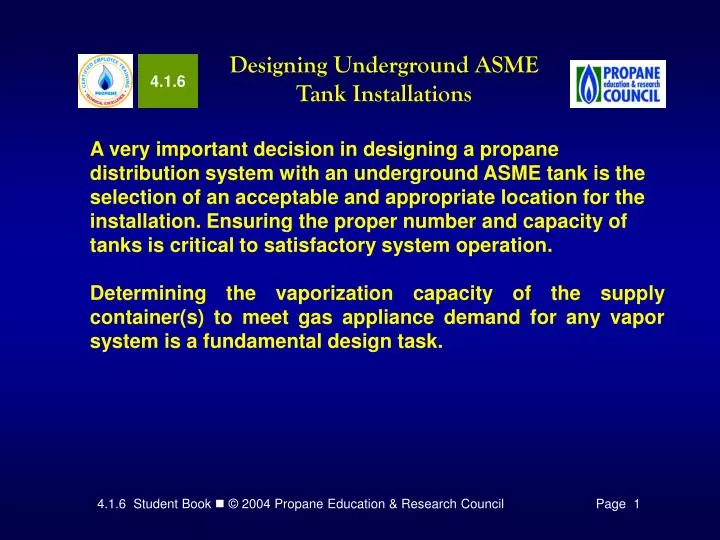
4.1.6 Designing Underground ASME Tank Installations A very important decision in designing a propane distribution system with an underground ASME tank is the selection of an acceptable and appropriate location for the installation.Ensuring the proper number and capacity of tanks is critical to satisfactory system operation. Determining the vaporization capacity of the supply container(s) to meet gas appliance demand for any vapor system is a fundamental design task.
4.1.6 Designing Underground ASME Tank Installations • In this module you will learn to identify: • Regulations that govern underground ASME tank site selection • Steps to finalize an underground ASME tank location plan • Factors that affect underground tanks vaporization capacity • Criteria for sizing and selecting underground ASME tanks • Other considerations for selecting appropriate ASME tank sizes • Code requirements and components for underground ASME manifold tanks in vapor service • Components for typical vapor service manifold tank installations with single regulator configuration
Aboveground and underground ASME tanks shall be located no closer to important buildings, property lines that can be built upon, ignition sources and building openings than the minimum distances set out in NFPA 58. NFPA 58 NFPA 58 2004 2001 6.3 3.2.2 Regulations that Govern Tank Location Figure 1 presents, in table format, minimum required distances and a brief purpose or explanation of the requirement.
Regulations that Govern Tank Location Figure 1. Minimum Distance Requirements for Stationary ASME Tank Installations
Regulations that Govern Tank Location Figure 1. Minimum Distance Requirements for Stationary ASME Tank Installations
Regulations that Govern Tank Location Figure 1. Minimum Distance Requirements for Stationary ASME Tank Installations
Figure 2. Underground ASME Tank Minimum Separation Distances Regulations that Govern Tank Location Note 1: The relief valve, filling connection, and liquid fixed maximum level gauge vent connection at the container must be at least 10 ft from any exterior source of ignition, openings into direct-vent appliances, or mechanical ventilation air intakes. Note 2: No part of an underground container shall be less than 10 ft from an important building or line of adjoining property that may be built upon.
Steps to Finalize a Tank Location Plan Some propane marketers have detailed procedures for determining system layout. Always follow local guidelines. Remember, a competent and complete planning effort will produce a satisfied customer.
Underground Tank Vaporization Capacity Factors When a tank is sized for vapor service, the goal is to ensure that the vaporization rate of the tank, or withdrawal rate, is greater than the demand for propane. The following factors must be considered when selecting underground ASME tanks: • Vaporization of propane • Outside surface area of the tank • Level of liquid propane in the tank • Temperature surrounding the tank • Location of the tank • Depth of soil frost penetration
Underground Tank Vaporization Capacity Factors • Vaporization of Propane • Vaporization of propane results from a change in the physical state of the fuel, from a liquid state to a gas or vapor state. Whenever the change of physical state of any material occurs, a transfer of energy is required. • When heat energy is added to liquid propane, producing a temperature above -44°F at atmospheric pressure, vaporization occurs changing the liquid propane to a vapor state. • Vaporization will occur in a sealed container at higher temperatures when a decrease in vapor pressure occurs due to appliance demand. • Severe service conditions combined with a high demand gas appliance load can lead to insufficient vaporization, decreased gas volume and pressure, and improper appliance operation.
Underground Tank Vaporization Capacity Factors • Outside Surface Area of the Tank • The heat required to vaporize liquid is transferred through the walls of the tank. The most important part of the tank, in this case, is the area of the tank that is in contact with the propane liquid (wetted surface area). • If the area of the tank in contact with the propane liquid (wetted surface area) is large, the total heat that can be transferred to the liquid is higher than that available with a tank having a smaller wetted surface area.
Underground Tank Vaporization Capacity Factors Level of Liquid Propane in the Tank Figure 3.
Underground Tank Vaporization Capacity Factors Temperature Surrounding the Tank Heat for vaporizing liquid propane in an underground tank is available from the surrounding soil, provided that the tank is installed below the level penetrated by frost in winter and early spring. In areas with shallow ground frost penetration, the temperature of soil can be relied upon to supply heat at temperatures near 50° F.
Underground Tank Vaporization Capacity Factors Location of the Tank As illustrated in Figure 4, tank depth and the depth of frost penetration affect soil temperature. As a result, a mounded underground tank placed nearer the overall grade of the surrounding soil will experience colder temperatures than an underground tank buried at a greater depth below soil grade.
Underground Tank Vaporization Capacity Factors D = Depth from Soil Grade Figure 4. Relationship of Effective Soil Depth for Buried Tanks Compared to Mounded Tanks
Underground Tank Vaporization Capacity Factors Figure 5. Underground Tank Riser Heights Affects Tank’s Buried Depth
Underground Tank Vaporization Capacity Factors Depth of Soil Frost Penetration Along the northern tier of states in the United States, in Canada and Alaska, average frost penetration depths may exceed 100 inches or more. As a general rule, small propane tanks (120-1,000 water gallon capacity) should not be used as buried or mounded supply containers for vapor distribution systems with high continuous Btuh demand in locations where the anticipated frost depth line exceeds 72 inches.
Underground Tank Vaporization Capacity Factors Figure 6. Average Frost Penetration Depth: Continental United States
Underground Tank Vaporization Capacity Factors Depth of Soil Frost Penetration • Frost penetration in soil depends mainly on the following factors: • Winter air temperature • Type of soil • Snow cover • Dry soils tend to freeze deeper and faster than wet soils. Snow cover acts as an insulator between the air and soil. Maximum frost penetration typically occurs in early spring.
Underground Tank Vaporization Capacity Factors Depth of Soil Frost Penetration Note: Frost penetration depth is important when selecting underground tanks. Do not undersize an underground tank, nor attempt to use a buried or mounded tank in a location where it is likely that a frost line will develop on the tank surface where vaporization of propane occurs. If undersized by as little as 50 Btu/hr, a frost line could develop on the tank and the vaporization rate will drop off to zero. If this occurs, the tank must be replaced with a larger tank.
Criteria for Sizing & Selecting Underground Tanks Sizing Buried Underground ASME Tanks The following method for sizing buried underground tanks (Figure 7) requires application of two factors concerning the vapor distribution system: • Total demand of all existing and anticipated future gas appliances connected to the underground tank(s). (For the method used in this training course, do not make any adjustments for appliance load factors; instead use the totalsystem demand.) • Maximum anticipated soil frost penetration depth for the installation location. Figure 7. Illustration of Depth from Grade to Bottom of Tank
Sizing Buried Underground ASME Tanks Figure 8 lists the vaporization rate of various ASME tanks when buried underground. Note that the estimated vaporization rate is calculated based on the soil frost line depth. The Btuh ratings are based on the tank being at least 25% liquid filled, and that the tank is buried to a depth not less than that shown below the chart for each tank size.
Sizing Buried Underground ASME Tanks Figure 8.
Sizing Mounded Underground ASME Tanks A mounded tank is one that is installed higher than a buried tank relative to the prevailing soil grade, and covered with fill soil, forming a raised mound above prevailing soil grade (Figure 9). Figure 9. Illustration of Depth from Grade to Bottom of Tank
Sizing Mounded Underground ASME Tanks Figure 10 lists the vaporization rate of various ASME tanks installed as mounded underground tanks. Note that the estimated vaporization rate is calculated based on the soil frost line depth. The Btuh ratings are based on the tank being at least 25% liquid filled, and that the tank is buried to a depth not less than that shown below the chart for each tank size.
Sizing Mounded Underground ASME Tanks Figure 10.
Sizing Mounded Underground ASME Tanks If none of the tanks listed for either mounded or buried underground tanks can supply the proper amount of vapor, there are three options: • Manifold two or more tanks together. • Choose a larger capacity tank. • Convert to liquid withdrawal tank and use a vaporizer. Unless the customer specifies an underground tank for landscaping reasons, if an auxiliary vaporizer is required, an aboveground ASME supply tank should be used due to the difficulty of withdrawing liquid from an underground tank without the use of a liquid pump specially designed for use with underground tanks.
Other Considerations in Tank Selection Frost Lines — The first consideration for proper tank sizing with regard to vaporization capacity is to ensure that the tanks that are installed do not develop a frost line under peak demand and severe operating conditions. If the supply tank(s) consistently develop a frost line when the liquid level is above 20%, the tank is too small for the load, and larger tank(s) should be installed (possibly at a greater depth). Efficient and Reliable Delivery Schedule— Figure 11 can be used to estimate the initial frequency of required delivery scheduling for a customer account.
Other Considerations in Tank Selection Figure 14. Example of a Delivery Scheduling Chart
Other Considerations in Tank Selection • Summary of Sizing Considerations — • Proper selection of ASME tanks is one key to customer satisfaction. • Tanks must be sized using the most severe anticipated conditions. • Preparing a gas customer profile provides important information, and knowing how the customer gas appliances will be used are the basis for sizing and selecting propane supply tanks. • Supply tank selection must consider any critical service factors. • If the supply tank(s) are not capable of supplying sufficient volume of vapor at the minimum required supply pressure (10 psig), auxiliary vaporizing equipment should be used.
NFPA 58 NFPA 58 2004 2001 5.7.7.1(F) 2.3.3.2(a)(4) Code Requirements for Manifold Tank Installations Most propane system installers and jurisdictional authorities interpret 2.3.3.2 (a)(4) as a requirement for excess-flow protection in manifold tank installations where the first-stage regulator is connected to tank service valves using vapor piping longer than the pigtail used in typical single tank installations and where the regulator is installed outside of the tank dome.
Figure 14. POL Back Check Tee Figure 13. Excess-Flow POL Fitting Selecting Components for Manifold Tank Installations Figure 12. Manifold Underground ASME Tanks
Selecting Components for Manifold Tank Installations • Special components for manifold underground tank installations: • Regulator vent pipe-away assembly • POL back check tees • Open-bottom water meter or valve box, or poured-in-place concrete vault with loose-fitting manhole cover
Time to See If You Got the Key Points of This Module… • Complete the Review on pages 18 -21. • See if you are ready for the Certification Exam by checking off the performance criteria on pages 22 & 23.