Download
1 / 69
780 likes | 1.23k Vues
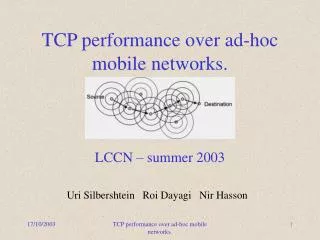
TCP Over Wireless Ad-hoc Networks. Vinay Sridhara vsridhar@usc.edu Nagendra Subramanya nsubrama@usc.edu. Wired Vs Wireless.

E N D
Vinay Sridhara vsridhar@usc.edu Nagendra Subramanya nsubrama@usc.edu
Wired Vs Wireless • In wired LANs, an address is equivalent to a physical location. This is implicitly assumed in the design of the wired LANs. In wireless, the addressable unit is the station. The station is a message destination, but not a fixed location. • Use a medium that has neither absolute nor readily observable boundaries outside of which stations with conformant physical transceivers are known to be unable to receive network frames
Continued.. • They are unprotected from outside signals . • Have dynamic topologies. • They lack full connectivity and therefore the assumption that one station can hear every other station is invalid. • They have time varying and asymmetric propagation properties.
802.11 • Main purpose is to provide the MAC and physical layer specification for wireless. • Permits the operation of an IEEE 802.11 conformant device within a wireless local area network that may coexist with multiple overlapping IEEE 802.11 conformant devices. • Describes the requirements and procedures to provide privacy of user information being transferred over the wireless medium and authentication of IEEE 802.11 conformant devices.
A few terminologies of 802.11 802.11 Components • STA – Any mobile, portable or stationary terminal. • BSS – Basic service set. • The BSS is an entity which consists of several mobile stations that can interact with each other. BSS1 STA1 STA2 STA1 BSS2 STA2
Continued. • A BSS maybe comprised of only two mobile stations. • This is called a IBSS (Independent Basic Service Set). • This is the one that is called Ad – Hoc Networks. • A network composed solely of stations within mutual communication range of each other via the wireless medium • network is typically created in a spontaneous manner • The principal distinguishing char of an Ad Hoc network is its limited temporal and spatial extent
Continued. • Instead of existing independently, multiple BSSs may form a network. • The architectural component used to interconnect BSSs is the Distribution system (DS). • The access points are the stations used to connect BSSs to DS.
Continued. STA1 STA-C STA1’ • BSSs may generally overlap to provide continuous coverage in physical volume. • The BSSs could be physically disjoint. Logically there is no limit to the distance between BSSs. STA1 STA2 STA1’ STA2’
Continued. • ESS - The DS and the BSSs allow the IEEE 802.11 to create a wireless network of arbitrary size and complexity. • Stations within an ESS may communicate and Mobile stations may move from one BSS to another transparently to LLC.
Extended Service Set • The stations communicate to Access points which are part of a Distribution System • Access point serves the stations in a BSS The set of BSSs are called Extended Service Set (ESS)
Communication with external world • Portal – Is the logical point at which the MSDUs enter and leave the IEEE 802.11 network. • This portal provides logical integration between the IEEE 802.11 architecture and the existing wired LANs • The stations act as both AP and portal when the DS is a wired network.
Services • The services provided by the 802.11 are divided into two. • Those that are part of every STA, called Station services • Authentication • De-Authentication • Privacy • MSDU Delivery • The services provided by the DS are known as the Distribution system service. • Association • Disassociation • Distribution • Integration • Reassociation
MAC layer Services • Services provided by the MAC layer • Security Services • Security is provided by the WEP (Wired equivalent privacy) • The security provided is limited to Station-to-Station exchange of data • The privacy service offered by the IEEE 802.11 WEP is the encryption of the MSDU • The security services provided are • Confidentiality • Authentication • Access control in conjunction with layer management.
Continued. • Asynchronous data services • Provided by the following three primitives. • MA-UNITDATA.request – generated by the LLC when an MSDU is to transmitted to the peer LLC. The format is as show below. MA-UNITDATA.request { Source address, Destination address, Routing information, Data, Priority, Service class }
MA-UNITDATA.indication – generated by the MAC sublayer entity to indicate to the LLC the arrival of a MSDU. MA-UNITDATA.indication { Source address, Destination address, Routing information, Data, Reception status, Priority, Service class }
MA-UNITDATA-STATUS.indication - provides the LLC sublayer with status information of the corresponding MA-UNITDATA.request primitive. MA-UNITDATA-STATUS.indication { Source address, Destination address, Transmission status, Provided priority, Provided service class }
MAC header • The four address fields in the MAC header are used to indicate the BSSID, Source address, destination address, transmitting station address and the receiving station address. • The frame control field has the following format
Collision Avoidance - 802.11 • 802.11 uses a protocol scheme know as carrier-sense, multiple access, collision avoidance (CSMA/CA). • Avoidance scheme is used because it is difficult to detect collisions in the RF media. • Hence is interoperates with the physical layer by sampling the transmitted energy over the medium transmitting data. • The physical layer uses an algorithm for clear channel assessment (CCA) to determine if the channel is clear. • If the received signal is below a certain threshold the channel is declared clear.
Station A Station B Station C Why Do We Need RTS/CTS ? • Used because of the Hidden terminal problem. • It occurs when there is a station in a service set that cannot detect the transmission of another station, and thus cannot detect that the media is busy
What Does RTS/CTS Do? • Communications is established when one of the wireless nodes sends a short message RTS frame. • The message duration is known as the network allocation vector (NAV). This alerts to back off during the transmission time. • The receiving station issues a CTS frame which echoes the senders address and the NAV. • If the CTS frame is not received, it is assumed that a collision occurred and the RTS process starts over.
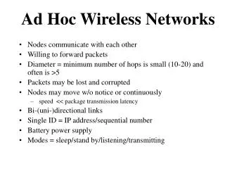
Characteristics of Wireless Networks • Limited bandwidth • High latencies and bit-error rates • Mobility
Difference between General wireless networks and Ad-Hoc Networks ? • Absence of a central base station • Frequent route re-computation • Network partitions • Multi-path routing algorithms
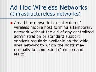
What is an Ad-Hoc Network? • AD-HOC network is a collection of mobile nodes with wireless network infrastructure capable of organizing themselves into a temporary network without the aid of any centralized network manager. • According to the IETF definition, a mobile Ad Hoc network is an autonomous system of mobile routers (and associated hosts) connected by wireless links--the union of which form an arbitrary graph.
SOURCE DESTINATION AD-HOC Networks
Implications of using Normal TCP over Ad-Hoc Wireless N/W • TCP does not distinguish between congestion and packet loss due to transmission errors and route failures • This inability results in performance degradation in ad hoc networks
Implications of using Normal TCP over Ad-Hoc Wireless N/W • Route re-computation takes a finite amount of time • During this time no packet can reach the destination through the existing route • Packets and ACKs may get queued and possibly dropped • In turn leads to timeouts at the source, which is misinterpreted as congestion
Consequences • Source retransmits unACKed packets • Invokes congestion control • Enters slow start recovery • These are undesirable because? • Why retransmit when there is no route • Retransmission wastes power and bandwidth • Low throughput as a result of slow start recovery after route restoration (this is actually desirable. Why?)
Why use TCP at all in such cases ? • For seamless portability to applications like file transfer, e-mail and browsers which use standard TCP
Different approaches to improve the performance of TCP over Ad-Hoc Networks • Last hop wireless networks • I-TCP • Snoop TCP • M-TCP • Freeze-TCP • Ad hoc networks • TCP-F • ELFN • ATCP
Indirect TCP (I-TCP) Connection between end points split into separate connections • No need of changes in TCP on wired hosts • Transmission errors on wireless link not propagated to wired network • Different optimal transport layer protocol between BS and MH • Loss of E2E semantics of TCP • Increased hand-off latency • Copying overhead
Snoop TCP BS caches packets from sender Performs local re-transmissions • Preserves E2E TCP semantics • Only BS needs to be changed • Doesn’t isolate behavior of wireless link as good as I-TCP • MH may need to be modified to accept NACKs • Snooping and caching may fail if E2E encryption schemes are used
M-TCP Same as I-TCP, but the BS is known as SH SH holds back ACK to the last byte Uses this ACK to freeze the sender when disconnection is detected • Maintains E2E semantics • Avoids useless re-transmissions and slow-starts • SH doesn’t buffer data • Needs a bandwidth manager to implement fair sharing over the wireless link
Freeze-TCP The client freezes the sender when it detects possible hand-off or predicts a temporary disconnection • No need of base station • Only mobile client’s TCP needs to be changed • Can be used with encrypted data • MAC has to detect future interruptions • Freezing fails when encryption scheme uses timestamps • Re-transmission restarted with old CWND
SOURCE DESTINATION X Network state after a while
TCP-Feedback (TCP-F) K. Chandran, S. Raghunathan, S. Venkatesan and R. Prakash
TCP-F: Introduction • ECN is not used. Why? • Instead uses Route Failure Notification (RFN) packet to inform source when route is disrupted • And Route Reestablishment Notification (RRN) packet informs the source when route is reestablished
TCP-F: Protocol • Failure Point (intermediate node) detects the route disruption • Explicitly sends RFN to source and records the event • Each intermediate node that receives the RFN: • Invalidates the particular route • If it knows of an alternate route, that route is used for further communication and RFN is discarded • Else, RFN is propagated towards source
TCP-F: Protocol (contd.) • On receiving RFN, source goes into “snooze” state
TCP-F: Protocol (contd.) • Source when in “snooze state” • Stops sending further packets • All existing timers are marked invalid • Send window and other state variables (RTO, etc) are frozen • Starts a route failure timer whose timeout = worst case route reestablishment time. Why? • Stays in this state till it receives an RRN packet
TCP-F: Protocol (contd.) • One of the intermediate nodes that had previously forwarded RFN learns about a new route • Sends an RRN to the source • Further RRNs received by this node for the same source-destination pair are discarded • Other nodes simply forward RRN towards the source • Source on receiving RRN • Changes to active state • Flushes out all unACKed packets in its current window
TCP-F: Conclusion • Communication resumes at the same rate as before the route failure occurred • There is no unnecessary loss of throughput • Is this ok? • Use of an additional packet RRN. Is it really needed? • Simulation environment • Based on a simple one-hop network • Links failed/recovered according to an exponential model • Routing protocol was not simulated
TCP-F: Conclusion • Overhead on routers • Detect route failures and reestablishments • Provide feedback to the source • Store the source id after forwarding an RFN so that it can send an RRN on finding a route • The paper does not discuss about multiple flows • Enhancements • Buffering at intermediate nodes
TCP with Explicit Link Failure Notification (ELFN) G. Holland and N. Vaidya
ELFN: Introduction • DSR complicates the situation – stale routes may be cached and propagated • Throughput is degraded • Turning of caching works only with single TCP connection • What if there are more sources?
ELFN • Similar to TCP-F • “Expected throughput” – throughput of a static wireless network • ELFN is piggy-backed to DSR’s route failure message • ELFN has a payload similar to that of “host unreachable” ICMP message
ELFN: Protocol • TCP sender receives ELFN • Disables congestion control mechanism, enters “stand-by” mode • Sends probes • On receiving an ACK for a probe, leaves “stand-by” mode
ELFN: Variations • Time interval between probe packets • greater it is, slower is the route discovery • smaller it is, causes congestion • best would be to have it as a function of RTT