Download
1 / 32
410 likes | 682 Vues
BASIC Electronics. Reporters: Hannah Faith Martinez Candy Amor Uriarte Ma. Dores Virtudazo Mika Aisha Mimura . Objectives of this Chapter. Understand basic electronic terms like current, voltage, resistance and power Solve circuits using Ohm’s Law Learn how to read schematic diagrams

E N D
BASIC Electronics Reporters: Hannah Faith Martinez Candy Amor Uriarte Ma. DoresVirtudazo Mika Aisha Mimura
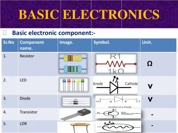
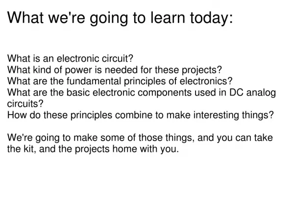
Objectives of this Chapter • Understand basic electronic terms like current, voltage, resistance and power • Solve circuits using Ohm’s Law • Learn how to read schematic diagrams • Become familiar with the usage of electronic devices • Enumerate the usage of the following electronic devices: resistors, voltage sources, capacitors, switches, diodes and transistors • Apply the knowledge of electronic circuits to practical applications • Introduce you to digital electronics by using logic gates learning how to read integrated circuit packages • Realize the importance of safety when handling electronic equipment and other electronic devices
Introduction • So far we have only looked at electric charges sitting still and static discharges. When we count on the charges moving through circuits, we start looking at electrical currents, voltages, resistances and capacitances, and how they behave in some materials. • Electronics comes from the word electron. This involves the flow of electrons across a material. From this we can define electronics.
Electronics – study of the properties and behavior of electrons in various materials. By knowing how these particles behave, we would be able to determine the effect of a material, either by itself or as part of an entire circuit.
Electronic materials • Materials in electronics are classified as to how they readily allow charges like electrons to flow through it. These are classified into four major groups. These are: • Conductors – materials that readily pass charges across them, with very little resistance. • Insulators – materials that totally prevents charges from passing through it. • Semiconductors – materials that allow only some of the charges to flow through. • Superconductors – materials that totally allow current to pass through, without any form of resistance.
current • It is the rate of the flow of charges, measured in amperes (A). • The unit of measurement for current is the Ampere, or Amp for short, and abbreviated as A. The name Ampere comes from Andre Marie Ampere who played with electricity as a small boy in Vermont. Q i = t
One ampere (A) is equal to one coulomb (C) of charge passing a point in a circuit in one second. (1A = 1C/s.). 1C = 6 x 10^18 electrons. Since we use positive values as our reference, the arrow indicating current is actually the direction of flow of positive charge, which is exactly opposite the direction of the flow of electrons. [The coulomb (named after Charles-Augustin de Coulomb, unit symbol: C) is a fundamental unit of electrical charge, and is also the SI derived unit of electric charge (symbol: Q or q). It is equal to the charge of approximately 6.241×10¹⁸ electrons.]
Currents in the ampere range are very fast. Although this is the standard unit, actual circuits, especially small devices use current lower than 1 Ampere. So in some cases, we use the milliampere or mA to measure current. • The milli means divided by 1000, so 0.001 Amps equals 1 milliAmp (1 mA) since 1 / 1000 = 0.001. Also, 0.5 Amps equals 500 milliAmps (500mA) since 500 / 1000 = 0.5.
voltage • The volt is named after the Italian physicist Allesandro Volta who did research with some of the original batteries. Voltage is a measure of the energy available to produce a flow of charges through a circuit. • Voltage or potential difference is a measure of the work done on a charge and is measured in volts (V).
Mathematically, V = W/Q • One volt is equal to one joule of work per coulomb of charge. (1V = 1J/C). Just as heat flows through a heat conductor until there is no longer a temperature difference, charge wants to flow through an electrical conductor until there is no more potential difference (voltage). • A measurement of voltage is much like a measurement of height. It gives you the difference in voltage between those two points. If point A is at 10 volts and point B is at 2 volts then the voltage measured between A and B is 8 volts (10 - 2).
When we measure voltage, our reference point is usually called ground or GND. This is because in some voltage sources, you really get the “voltage of the ground” by connecting a metal pipe or other conductor to the ground. This is our zero (0) volts, the ground.
capacitance • It is a measure of the ability to store charge and energy in electric fields. • To measure capacitance of a material, if a voltage V is attached to the material, the capacitance C depends on this equation: • Where Q is the charge in coulombs, C is the capacitance in farads and V is the voltage of the battery in volts. [The farad (symbol: F) is the SI derived unit of electrical capacitance. It is named after the English physicist Michael Faraday.] Q C = V
The energy in joules stored in a capacitor when it is charged up to a voltage V is 1 E = CV² 2
RESISTIVITY, RESISTANCE, AND LOADS • Resistivity is the property of a material that is a measure of the ability to resist the flow of charges. This is dependent on the temperature o the material. • Resistance is the characteristic of a material of a given dimension, a measure of the ability to resist the flow of charges. • In equation form,
If conductivity is the inverse of resistance, the inverse of resistance is conductance. • Resistance (R) is measured in ohms (Ω). The Ohm is named after a German physicist, Georg Simon Ohm, who tested different wires in circuits to see what effect the wire’s resistance had on the current that would flow. Resistivity, on the other hand has the unit ohms-m or ohm-centimeters.
From the equation of Resistance, it is proportional to the length of the conductor L, inversely proportional to the cross-sectional area A of the conductor, and depends on the material used for the conductor (its resistivity ). • Gold is the best conductor and has the lowest resistance, closely followed by copper which has a bit higher resistance. Resistance is also a measure of how much of the energy of the current is converted into heat during the process of flowing.
Ohm’s law • There is a simple relationship between current, voltage and resistance. This relationship is called Ohm’s Law. In equation form, Voltage = Current x Resistance V = i x R Where i is the current in Ampere (A) V is the voltage in Volts (V) R is the resistance in Ohms ()
Example 1 • What is the voltage across a material if the current flowing through it is 2 amperes and the resistance is 100 ohms? Given : current i : 2A resistance : R 100 Ω Find : Voltage (V) Solution : Using Ohm’s Law, V = iR = 2A ( 100 Ω ) = 200 Volts
Example 2 • How much current is flowing through a material whose resistance is 1000 Ohms and the voltage across is 10 Volts? Given : Voltage V = 10 V resistance = R 1000 Ω Find : Current (i)
Solution: From Ohm’s Law, V = iR When solving for i, i = V/R. So, i = V/R = 10 V/(1000 Ω) = .01 A or 10 milliAmperes (mA)
Example 3 • What is the resistance of a material in kiloohms if the voltage across is 5 Volts and the current flowing through it is 20 mA? Given : Voltage V = 5 V current i= 20 mA Find : Resistance in kiloohms If the current is in milliamperes and the voltage is in volts, the resistance will be in kiloohms (kΩ)
Solution : From Ohm’s Law, V = iR. When solving for R, R = V/i. So R =V/I = 5 V /(20 mA ) = 0.25kΩ If you want it in ohms, just multiply by 1000, so R = 250Ω
Electric power • From the previous chapters, we have defined power as P = W/t • Where P is the power in watts, W is the work in joules and t is the time in s. • Since we defined voltage as V = W/Q, we can replace W with VQ P = W/t = VQ/t • But Q/t is just the current i, so our equation for current becomes any of the following: P = Vi = i²R = V²/R
EXAMPLE • How much power is consumed by a material if the voltage across is 5 V and the current flowing through it is 2 A ? Given: Voltage V = 5 V current i = 2 A Find: Power
Solution Since what is given is V and i. To solve for P, we will use equation: P = Vi = 5V (2A) = 10 W The material consumes 10 Watts of Power.
energy • Since by definition, Work equals energy, then W = E = Pt • Substituting this equation : P = Vi for P, we can also express the energy as E = V i t
The electric circuit • When combining electronic elements together for a purpose, you form an electronic circuit. An electronic circuit is a connection of electronic components forming a closed figure, or a loop. The Minimum Circuit • To demonstrate what a circuit is, let us consider this example on the board. This makes use of a voltage source, and a resistance source. The current will just be a factor of the voltage and resistance. Current will flow because all the elements are connected and they form a loop.
Open Circuit • An open circuit is when two points are not connected by anything. No current flows and noting happens. If a wire in your vacuum cleaner breaks it can cause an open circuit and no current can flow so it does not do anything. There may be a voltage between those two points but the current ca not flow without a connection. • An open circuit provides no path. It is equivalent to an infinitely large resistance in the circuit and no current flows.
Short Circuit • A short circuit (or short) occurs when two points with different voltage levels are connected with no resistance between two points. This can cause a large amount of current to flow. • You will quickly know a short when you accidentally connect your fingers with a battery through a wire. The wire will heat up and burn your fingers, and the battery will quickly wear out. • If a short circuit happens in your house, it will usually cause a circuit breaker to break or a fuse to blow up. If there is no device to limit the current, the wires may melt and cause a fire. • When a person is electrocuted, it doesn’t just harm the person, it also causes a short circuit.
Using the breadboard (socket board) • The breadboard is a gadget that allows you to connect different electronic components easily and safely. This is also called a prototype board, where you test the electronic design and make refinements before putting the components in a circuit board. • The breadboard has many strips of metal (copper usually ), which run underneath the board.
These strips connect the holes on the top of the board. This makes it easy to connect components together to build circuits. To use the breadboard, the legs of components are placed in the holes (the sockets). The holes are made so that they will hold the component in place. Each hole is connected to one of the metal strips running underneath the board. Each wire forms a node. A node is a point in a circuit where two components are connected. Connections between two different components are formed by putting their legs in a common ode. On the breadboard, a node is the row of holes that are connected by the strip of metal underneath.
The long top and bottom row of holes are usually used for power supply connections. • The rest of the circuit is built by placing components into the holes and connecting them together with jumper wires. Then, when a path is formed by wire and components from the positive supply node to the negative supply node, we can turn on the power ad current flows through the path and the circuit comes alive. • For chips with many legs (ICs), place them in the middle of the board so that half of the legs are on one side of the middle line and half are on the other side.