Download
1 / 33
330 likes | 455 Vues
SWT - Diagrammatics. Lecture 3/4 - Diagramming in OO Software Development - partA 2-May-2000. Previous Lecture Review. Diagram Distinctions : Adjoinment, Linkage, Containment. Diagram Taxonomies. Diagram use in Computer Science :

E N D
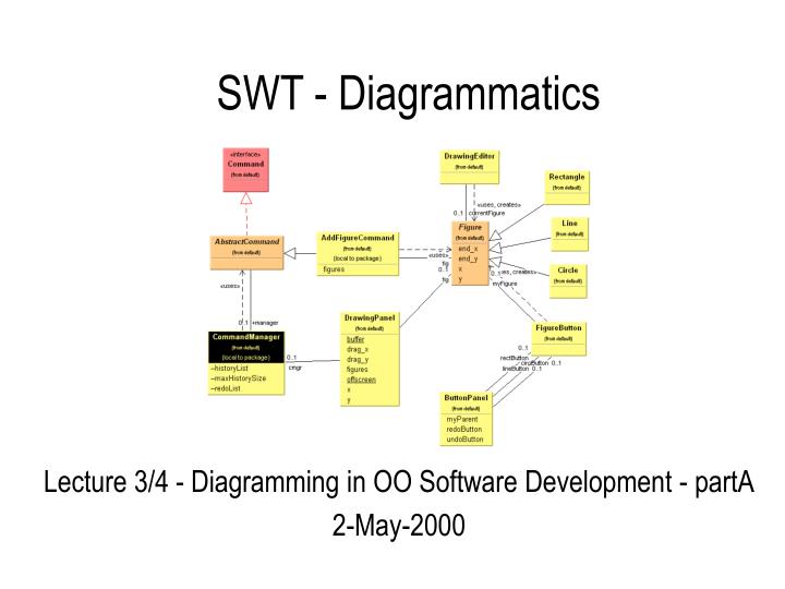
SWT - Diagrammatics Lecture 3/4 - Diagramming in OO Software Development - partA 2-May-2000
Previous Lecture Review • Diagram Distinctions : • Adjoinment, Linkage, Containment. • Diagram Taxonomies. • Diagram use in Computer Science : • Venn, Flowcharts, NSD’s, Structure, Dataflow, ERD’s, Cell and Arrows, State, Petri nets. • Logic Gate Diagrams. • How to operate Theseus under CM.
Overview • OO Introduction, • OO Design Notations, • Objects, Messages / Control & Data Flow, Classes. • Class Attributes and Operations, • Visibility of Attributes and Operations, • Relationships : • Association, Multiplicity, Aggregation, • Dependency, Inheritance. • Object Oriented Views
What OO Systems are? • OO Systems are viewed as compositions of domain specific object abstractions, rather than data and functions. Objects associate data and behaviour. • Objects in a System inter-communicate by sending messages to each other. • An Object is a domain concept that has : • State • Behaviour • Identity
OO Software Engineering • has three distinctive OO processes : • OO Analysis (OOA) focuses on the understanding of real-world models. • OO Design (OOD) stresses the mapping of the OOA model to structured architectures, and • OO Programming (OOP) deals with the building of OOD models under the constraints of the existing environments.
The Object Model Is a view of the world in terms of Objects and their relationships.
Object Oriented Design Notations • OOD is one of CS’s disciplines that make heavy use of diagrams. • There are many different OOD notations, all conveying the same (more or less) information about the systems they describe : • Coad/Yourdon, Fusion, Jacobson, Martin/Odell, Shlaer and Mellor, Wirfs-Brock et al, Meyer etc • Three are the most popular ones : • Booch,OMT, UML. • You can use which ever you prefer, however UML became the standard in OO design on feb’97.
Objects • An object is an atomic entity, formed from the union of state and behaviour. • Provides encapsulation. • Provides a weak coupling with the outside world. • Software objects define an abstract representation of real or virtual world entities. Visible behaviour An object Hidden internal state
Objects • In Booch, objects are represented by clouds. • In OMT as in UML, objects are represented by rectangles. • In UML, the name of the object is underlined. Booch OMT UML Name : Class Name : Class Name : Class
Messages / Control & Data Flow • The message is the unit of inter-object communication. • It allows interaction in a flexible manner. • It is responsible for the delegation of tasks, and guarantees that constraints are satisfied. • A message combines control flows and data flows within a single entity. • The notion of a message is an abstract concept: it could be a constructor, a method call, a discrete event, an interrupt, a UDP datagram etc. Message A Control Flow Object1 Object2 Data Flow Data Flow
Messages / Control & Data Flow • In the three notations, messages are represented using arrows near the links. • The control flow type is represented by using a line decorated with an arrowhead. • A small circle connected to the line indicates a data flow, with the arrow pointing to the direction of the flow. • This notation is optional and has become redundant. Booch OMT UML Data flow represented by the message labels
Classes • A class is the product of an abstraction process which starts with the identification of common characteristics of a set of elements, and proceeds to the concise description of these characteristics. • The abstraction process is arbitrary: it is defined with respect to a particular viewpoint A Class
Classes • A class describes the definition domain of a set of objects. • It acts as a “mould” from which objects can be created. • Software objects are built from the class, via a process called “instantiation”, objects are “instances” of classes. • In Booch, classes are represented using dotted clouds. • In OMT, as in UML, classes are represented using rectangles. Booch OMT UML Class Class
Class Attributes and Operations • Each class is represented as a rectangle subdivided into three components : • The name of the class, • The attributes of the class, • The operations of the class, • By default, attributes are hidden and operations are visible. • These compartments may be omitted to simplify the diagrams. Class name Attributes Operations( )
Class Attributes and Operations • In all three notations, attributes and operations are represented within the class glyph. • Some attributes can be hidden for the sake of readability. • OMT and UML use boxes to distinguish the attributes from the operations. Booch OMT UML Class name Class name Class name Attributes Attributes Attributes Operations( ) Operations( ) Operations( )
Visibility of Attributes and Operations • Visibility rules complement and refine the concept of encapsulation. • It is possible to customise the degree of protection to the benefit of a class client by declaring attributes as public, protected or private. • One of the benefits of breaking encapsulation can be, for example, to reduce the time required to access attributes by making unnecessary to call setters/getters. Could this be a right decision? Class name + Public Attribute # Protected Attribute - Private Attribute + Public Operation( ) # Protected Operation( ) - Private Operation( )
Visibility of Attributes and Operations • The three notations encompass public, protected and private levels of protection. • Booch provides an additional “implementation” level. Booch OMT UML Nothing public | protected | | private | | | implementation Nothing unspecified + public # protected - private + public # protected - private Class name Class name Class name + Public Attribute # Protected Attribute - Private Attribute + Public Attribute # Protected Attribute - Private Attribute Public Attribute | Protected Attribute | | Private Attribute Public Operation( ) | Protected Operation( ) | | | Private Operation( ) + Public Operation( ) # Protected Operation( ) - Private Operation( ) + Public Operation( ) # Protected Operation( ) - Private Operation( )
Relationships: Association • The association relationship expresses a bi-directional, semantic connection between classes. • An association is an abstraction of the links that exist between object instances. • It is possible to specify the role of a class within an association. • A role name may be specified on either side of the association. Dean University Student
Relationships: Association • In all the three notations, an association is represented by a continuous line between the classes that participate in it. Booch OMT & UML University Student University Student
Multiplicity • Relationships between classes carry multiplicity information that specifies the number of instances that participate in the relationship • The table below summarises the most common multiplicity values : Symbol Meaning 1 One and only one 0..1 Zero or one M..N From M to N (natural integers) * From zero to any positive integer 0..* From zero to any positive integer 1..* From one to any positive integer Dean 1 1 University 1 0..* Student
Multiplicity • OMT proposes a graphical representation based on circles. • Take care not to confuse these circles with those meaning has and uses in Booch, as there is no relationship between these two representations. Booch OMT UML 1 by default 1 0..1 N 3..5, 7, 15 3..N 0..N 1 0..1 * 3..5, 7, 15 3..* 0..1 1+ 3..5
Relationships: Aggregation • An aggregation is a particular kind of association that expresses a stronger coupling between classes. • Aggregation allows the representation of relationships like “master and slave”, “all and part of” and “composed of and components”. • It is commonly referred to as a “HasA” (or “HasMany”) relationship. Car 1 Engine 1
Relationships: Aggregation • There is no strict equivalence between the Booch, OMT and UML notations. • As aggregation is concerned, Booch is closer to the design phase, OMT is closer to the analysis stage, and UML covers both. • 2 cases are illustrated for each design methodology : aggregation by reference and aggregation by value (same in OMT) Booch OMT UML Car Engine Car Engine Car Engine Car Engine Car Engine Car Engine
Relationships: Dependency • A dependency is a “loose” association that expresses a weaker coupling between classes. • Usually dependency shows that a class uses another class with one way or another, maybe by using the other class’s static methods or by passing objects of the second class’s type to another object of another class. • It is commonly referred to as a “Uses” relationship. Assembler Robot 1 Car Parts 1..*
Relationships: Dependency • Booch represents a dependency using an association labelled with a small circle placed on the client side. • OMT represents a dependency using a dotted arrow with a filled head. • UML uses a dotted arrow with an open head. • In OMT and UML the arrow points to the supplier – the element being dependent on. Booch OMT UML Robot Parts Robot Parts Robot Parts
Shape is a Star Relationships: Inheritance • Inheritance is a technique offered by programming languages to construct a class from one or more (in C++) classes, sharing attributes, operations and sometimes constraints within a hierarchy of classes. • A class can specialise, extend, subclass, or be a child of another class.
Relationships: Inheritance • Inheritance propagates the characteristics of the parent class (depending on their visibility) into the child classes. • It is commonly read as an “IsA” relationship. Vehicle Car Bike Audi BMW Yamaha Suzuki
Relationships: Inheritance Booch OMT UML • In all three notations, inheritance is represented using an arrow that points from the subclass to the superclass. Vehicle Vehicle Vehicle Car Car Car Vehicle Vehicle Vehicle Car Bike Car Bike Car Bike Or as in OMT
Object Oriented views • Hierarchy view (usually static) : • classes, interfaces and their relationships. • Interaction view (usually dynamic) : • objects, method calls, events, messages. • Modules view : • name spaces, packages-libraries-modules, classes, and their internal and external dependencies.
Hierarchy View TestProgram has Drawable implements main() draw() • Inheritance, • Aggregation, • Uses. Shape draw() setOrigin() setColor() Relationships : is Rect Oval Line draw() toString() setText() draw() toString() setText() draw() toString() setText()
Interaction View myTestprogram myVector myEnum myShape • Is based on objects and method calls. • Depicts the runtime of the system. drawAll() elements() *[hasMoreElements()] nextElement() draw()
figures Module View tools • Package Visibility • Package Dependencies framework commands domain gui util