Download
1 / 21
210 likes | 215 Vues
Learn about the HMI investigation, its goals, and the team of researchers working to study the origin and variability of the Sun. Discover the data products and examples that contribute to our understanding of solar dynamics.

E N D
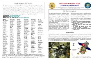
HMI Investigation Overview Philip Scherrer pscherrer@solar.stanford.edu 650-723-1504
HOP HEB SDO - Solar Dynamics Observatory • SDO will carry: • AIA - The Atmospheric Imaging Array • Lockheed Martin Solar and Astrophysics Lab • EUV – EUV Variability Experiment • University of Colorado • HMI – Helioseismic and Magnetic Imager • Stanford University with LMSAL SDO will be in an inclined geosynchronous orbit with data collected at White Sands NM and operations managed at GSFC.
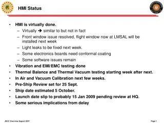
Goals for January 2005 Team Meeting • We are now just after the HMI Critical Design Review. • The flight instrument is being built and will be ready for optical testing this summer. • It will be delivered to NASA for integration onto SDO in November of next year. • Proposal was about three years ago and launch about three years away. • The data processing center design is near completion. • We are near the point where we will need to begin the process of incorporating analysis software. • The primary goals for this meeting are to: • Update the specifications for standard data products • Confirm Co-I plans for analysis software development • Encourage coordination in development of science analysis techniques • Update the Science Team on the project status • Clarify priorities for early science goals
HMI Institutional Roles LWS Science SDO Science HMI Science Team HMI Instrument HMI & AIA JSOC Stanford E/PO LMSAL The HMI Science Team includes 30 Co-Investigators and many Associate Investigators at 21 institutions in the US and abroad
Phil Scherrer HMI Principal Investigator Alan Title AIA Principal Investigator LMSAL Larry Springer HMI-AIA Prg. Mgr. Rock Bush HMI-Stanford Prg. Mgr. Romeo Durscher Admin Sasha Kosovichev HMI Science Lead Barbara Fischer HMI Deputy Prg.Mgr. Jesper Schou HMI Instrument Scientist Jim Lemen JSOC Ops Lead Phil Scherrer/20** Acting JSOC Data Lead Yang Liu Magnetic Field Science Jerry Drake Inst. Software Lead Margie Stehle Admin Support Carl Cimilucca JSOC System Engineer Rasmus Larsen Processing & Analysis Keh-Cheng Chu JSOC Hardware Rick Bogart Data Export Jim Aloise JSOC Software Jeneen Sommers Database & GUI TBD System Support Sebastien Couvidat Sci Prog Support Karen Tian VSO Access Hao Thai Data Operations TBD Sci Programmer SDO/HMI – Stanford Personnel
Investigation Overview The primary goal of the Helioseismic and Magnetic Imager (HMI) investigation is to study the origin of solar variability and to characterize and understand the Sun’s interior and the various components of magnetic activity. HMI makes measurements of the motion of the solar photosphere to study solar oscillations in order to determine the interior sources and mechanisms of solar variability It also makes measurements of the photospheric magnetic field in order to study how the physical processes inside the Sun are related to surface magnetic field and to enable estimates of the low and far coronal magnetic field for studies of variability in the extended solar atmosphere.
HMI Science Objectives – Top Level • HMI science objectives are grouped into five broad categories: • Convection-zone dynamics and the solar dynamo; • How does the solar cycle work? • Origin and evolution of sunspots, active regions and complexes of activity; • What drives the evolution of spots and active regions? • Sources and drivers of solar activity and disturbances; • How and why is magnetic complexity expressed as activity? • Links between the internal processes and dynamics of the corona and • heliosphere; • What are the large scale links between the important domains? • Precursors of solar disturbances for space-weather forecasts. • What are the prospects for predictions? • These objectives are divided into 18 sub-objectives each of which needs data from multiple HMI data products. • Progress requires a science team with experience in multiple disciplines.
B – Rotation Variations J – Subsurface flows C – Global Circulation I – Magnetic Connectivity A – Interior Structure D – Irradiance Sources E – Coronal Magnetic Field H – Far-side Imaging F – Solar Subsurface Weather G – Magnetic Fields HMI Data Product Examples • Sound speed variations relative to a standard solar model. • Solar cycle variations in the sub-photospheric rotation rate. • Solar meridional circulation and differential rotation. • Sunspots and plage contribute to solar irradiance variation. • MHD model of the magnetic structure of the corona. • Synoptic map of the subsurface flows at a depth of 7 Mm. • EIT image and magnetic field lines computed from the photospheric field. • Active regions on the far side of the sun detected with helioseismology. • Vector field image showing the magnetic connectivity in sunspots. • Sound speed variations and flows in an emerging active region.
Internal rotation Ω(r,Θ) (0<r<R) Global Helioseismology Processing Tachocline Meridional Circulation Internal sound speed, cs(r,Θ) (0<r<R) HMI Data Processing Data Product Science Objective Differential Rotation Full-disk velocity, v(r,Θ,Φ), And sound speed, cs(r,Θ,Φ), Maps (0-30Mm) Near-Surface Shear Layer Local Helioseismology Processing Filtergrams Activity Complexes Carrington synoptic v and cs maps (0-30Mm) Active Regions Sunspots High-resolution v and cs maps (0-30Mm) Irradiance Variations Doppler Velocity Magnetic Shear Deep-focus v and cs maps (0-200Mm) Observables Flare Magnetic Config. Far-side activity index Flux Emergence Line-of-sight Magnetograms Magnetic Carpet Line-of-Sight Magnetic Field Maps Coronal energetics Vector Magnetograms Vector Magnetic Field Maps Large-scale Coronal Fields Solar Wind Coronal magnetic Field Extrapolations Continuum Brightness Far-side Activity Evolution Predicting A-R Emergence Coronal and Solar wind models IMF Bs Events Brightness Images HMI Data Products and Objectives Version 1.0
HMI-AIA Joint Science Operations Center • HMI and AIA SOCs have been merged to form a JSOC • Components of the JSOC will be at both Stanford and Lockheed-Martin Solar and Astrophysics Lab (LMSAL) • JSOC-Ops for both HMI and AIA at LMSAL • Data capture, pipeline processing, online archive, tape archive, export functions at Stanford. • HMI Higher level processing at Stanford • AIA Higher level processing at LMSAL • High-speed network connection between the two sites • The JSOC will be discussed in more detail as part of both the SDO CDR and the SDO ground system CDR next year
GSFC LMSAL White Sands housekeeping MOC House- keeping Database DDS HMI & AIA Operations Stanford HMI-AIA JSOC Pipeline Processing System Redundant Data Capture System Quicklook Viewing Primary Archive 30-Day Archive Local Archive AIA Analysis System Catalog High-Level Data Import Offline Archive Data Export & Web Service World Offsite Archive HMI & AIA JSOC Architecture Science Team Forecast Centers EPO Public
Telescope with polarization analysis Camera system Tunable narrow band filter Electronics to make it work SDO Computers Science Investigation MOC DDS Science Team, NASA, Taxpayers Schematic Diagram of HMI
Measure Here HMI – How It Works HMI consists of a telescope, tunable filter, camera, and necessary electronics. HMI repeatedly images the Sun in six polarizations at five wavelengths across a spectral line. The position of the line tells us the velocity while the shape changes of the line in different polarizations tell us the magnetic field direction and strength in the part of the Sun’s surface seen by each pixel. Long gap-free sequences of velocity images are needed to enable the techniques of helioseismology.
Magnetic Field Sample Profile HMI measures magnetic fields by sampling the Zeeman split line in multiple polarizations. The figure shows the five sample positions for a sunspot umbral field (about 3000G) with a 1000 m/s offset. The green and red curves are Left and Right circular polarized components and allow measurement of the line-of-sight projection of the field. Analysis of both polarizations is required to infer the Doppler velocity and line-of-sight magnetic flux. For vector magnetic fields two directions of linear polarization are added to infer the field direction. One HMI camera is used for velocity and LOS field, the other for vector fields.
Basic Requirements Sources • SDO Level 1 Requirements • SDO Mission Requirements Document (MRD) • Summary of spacecraft and instrument driving requirements • HMI Instrument Functional Specification • Top level instrument requirements – part of the HMI contract statement of work • HMI Instrument Performance Document (IPD) • Detailed HMI science drivers and flowdown to subsystem requirements • HMI Performance Assurance and Implementation Plan (PAIP) • HMI implementation of the SDO Mission Assurance Requirements • HMI to Spacecraft Interface Control Documents (HMI-S/C ICD) • Ground System Interface Control Documents
HMI “Level 1” Requirements To enable accomplishment of the science objectives of the investigation, the HMI instrument will produce measurements in the form of filtergrams in a set of polarizations and spectral line positions at a regular cadence for the duration of the mission that meet these basic requirements: • Full-disk Doppler velocity and line-of-sight magnetic flux images with 1 arc-sec resolution at least every 50 seconds. • Full-disk vector magnetic images of the solar magnetic field with 1 arc-sec resolution at least every 10 minutes. The HMI data completeness and continuity requirement is to capture 99% of the HMI science observables 95% of the time.
HMI Science Objectives Duration of mission Completeness of coverage HMI Science Data Products Roll accuracy Time accuracy (months) HMI Observation Sequences Duration of sequence Cadence Completeness data sequence Noise Resolution Time accuracy (days) HMI Observables Sensitivity Linearity Acceptable measurement noise Image stability Time rate (minutes) Orbit knowledge HMI Instrument Data Accuracy Noise levels Completeness of filtergrams Tuning & shutter repeatability Wavelength knowledge Image registration Image orientation jitter HMI Instrument Mass Power Telemetry Envelope Subsystem requirements CCD: Thermal environment ISS: pointing drift rate, jitter Legs: pointing drift range Source of HMI Requirements