Download

1 / 55
550 likes | 555 Vues
An introduction to fuel cells P. A. Christensen. Winshields Crag on the Roman Wall.

E N D
An introduction to fuel cells P. A. Christensen
Winshields Crag on the Roman Wall “For nearly 2000 years, Hadrian’s wall has brooded over the borderlands between Scotland and England. In that time, kings and queens have come and gone, empires have rose and fell, but not a single g of coal or ml of oil has been formed”
The fuel cell can trace its roots back to the 1800's. A Welsh born, Oxford educated barrister, Sir William Robert Grove, who practiced patent law and also studied chemistry or "natural science" as it was known at the time.
Grove realized that if electrolysis, using electricity, could split water into hydrogen and oxygen then the opposite would also be true. Combining hydrogen and oxygen, with the correct method, would produce electricity. 2H2O 2H2 + O2 E0 = 1.23V
To test his reasoning, Sir William Robert Grove built a device that would combine hydrogen and oxygen to produce electricity, the world's first gas battery, later renamed the fuel cell. His invention was a success, and Grove's work advanced the understanding of the idea of conservation of energy and reversibility. Grove's drawing of one of his experimental "gas batteries" from an 1843 letter
An early demise… …..and resurrection 1960
The world speed record in 1899, of 104 km h-1, was held by an electric vehicle, the “Jamais Contente”. In 1900 in the USA, there were 1681 steam-driven vehicles, 1575 electric vehicles and only 936 driven by petrol engines. All electric vehicles were powered by lead-acid batteries. A fuel tank is lighter than a lead-acid battery and can be ‘recharged’ more rapidly. A tank of fuel gives a much longer range than a fully charged battery- current target of 300 km Still remains elusive (battery should not exceed ca. 1/3 of total weight of vehicle). The advent of the self-starter (powered by a lead-acid battery!) finally clinched the relegation of electric vehicles to milk floats and fork-lift trucks.
In the late 19th and early 20th centuries, coal was king But all attempts to make coal fuel cells failed, and fuel cells fell out of favour until the 1960’s, due to interest from an out of this world source!
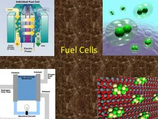
Products Oxidant e- Solid, liquid or polymer electrolyte H+ Anode Cathode Fuel Products The fuel cell concept
The electrolyte essentially: • Separates fuel and oxidant • Facilitates ion transport between anolyte and catholyte • Prevents electrical short circuit between anode and cathode • And can be liquid, solid or polymeric
O2 e- Pt Pt 2H2 4H+ + 4e- 4H+ + 4e- + O2 2H2O H+ Cathode (Pt catalyst) Anode (Pt catalyst) Electro lyte H2 H2O The simplest realisation – the H2/O2 fuel cell
FlowField Catalyst Layer Gases: Wettability Flooding/conductivity 3-phase interface Gas Diffusion Layer The structure of Gas Diffusion Electrodes (GDE’s) (Porous carbon area up to 1000 m2 g-1)
In aqueous solution H2 or O2 only soluble to ca. 1mM at 1 atm. E l e c t r o d e H2 or O2 Zone of high current density - 3 phase zone Electrolyte The three-phase zone in a gas diffusion electrode
Carbon + Pt Pore Gas space Electrolyte Carbon + Pt Reaction zone The three-phase zone in a single pore of a gas diffusion electrode
Thermodynamic cell voltage Ohmic loss Activation overpotential loss - catalysts Mass transport loss A typical (H2/O2) fuel cell voltage vs current plot
Sources of hydrogen 5% Electrolysis (wind, solar, wave, nuclear….) – expensive (operating cost 50p per kWh) but pure hydrogen 95% Reforming of organics -operating cost for H2 production 5p per kWh, but fuel cell system more complex and more expensive to construct. 650 – 850 C/Rh: CnH2n+2 + nH2O nCO + (2n+1)H2 CO + H2O CO2 + H2 (Methanol can be reformed at 300 C) Either high T or CO-tolerant anode catalysts. H2S can also be present in reformed fuel.
The most general fuel and oxidant are H2 and O2 (air). The highest temperature fuel cells (SOFC & MCFC) can use a variety of organics directly as fuels, whilst methanol is used in the low temperature Direct Methanol Fuel Cell. 1. Low temperature fuel cells
Alkaline Fuel Cells (AFC) • The simplest realisation of the fuel cell concept • Operates at 70 C, PTFE-bound porous carbon electrodes with Pt catalysts, 30% KOH electrolyte • Runs on pure H2 + pure O2 • Power generating efficiencies of up to 70%, 0.3 – 12 kW • Compact. • Small commercial units available up to 100 kW • High power/weight ratio (hence space application) • Produces pure water and heat • Low thermal signature, silent, pollution-free exhaust • Alkaline solution – do not need noble metal catalysts (Siemens: 1 mg cm-2 Ti-doped Raney Nickel/60 mg cm-2 Ag)
The Alkaline Fuel Cell (AFD) Gas Diffusion Electrode Electrode support KOH
AFC Problems • Use of KOH as electrolyte and air as oxidant leads to fouling by precipitation of K2CO3 • High efficiencies achieved with high catalyst loadings • H2O product dilutes KOH and reduces performance – hence needs water evaporator • CO or H2S in reformate poisons anode catalyst • £1500 - £2500 per kW; fuel cost £0.50 per kWh
Monday 13 April 1970, 9.07 pm 200,000 miles out in space O2 cryotank 2 explodes on Apollo 13
The Apollo fuel cell power plant. 31 cells, 100 mA cm-2, in total 1.12 kW at 28V. 110 kg
Solid Polymer Electrolyte (SPE) aka Polymer Electrolyte Membrane (PEM) Fuel Cells • Most favoured for traction (cars and buses) – small family car (800 kg unladen weight, 80 km hr-1 cruising speed) needs 6 – 12 kW. Otherwise military (submarine) and space • Runs on pure H2 + air/O2 • Operating T up to ca. 90 C, PTFE-bound porous carbon electrodes with Pt catalysts, Solid Polymer (Nafion) electrolyte • Small commercial units up to 500 W available
SPE Problems • £2500 - £5000 per kW; fuel cost £0.50 per kWh • Needs water separator • CO in fuel must be below 100 ppm
1Hydrogen is channelled through field flow plates to the anode on one side of the fuel cell, while oxygen from the air is channelled to the cathode on the other side of the cell 2At the anode, a platinum or non- platinum catalyst causes the hydrogen to split into positive hydrogen ions (protons) and negatively charged electron. 3The Polymer Electrolyte Membrane (PEM) allows only the positively charged ions to pass through it to the cathode. The negatively charged electron must travel along an external circuit to the cathode, creating an electrical current. Cathode Anode Hydrogen Air (Oxygen) H2→ 2H+ + 2e- ½O2 + 2H+ + 2e- → H2O Methanol CH3OH + H2O → 6H+ + CO2 + 2e- 4At the cathode, the electrons and positively charged hydrogen ions combine with oxygen to form water which flows out of the cell. PEM
Phosphoric Acid Fuel Cells (PAFC) • The only commercially available fuel cell (> 200 fuel cell systems have been installed all over the world) • Runs on H2, methane, natural gas + air/O2 • Generate electricity at > 40% efficiency (ca. 85% if the steam produced is used for cogeneration; cff ca. 35% for the utility power grid in the USA) • Graphite felt+low Pt loading, concentrated phosphoric acid (polyphosphoric acid) electrolyte absorbed in SiC • Operating temperatures 150 - 220 C • High O2 solubility • CO tolerant ca. 1 - 2 percent% due to higher operating T • Existing PAFCs have outputs up to 200 kW (11 MW units have been tested). Combined Heat and Power operation.
PAFC Problems • £2000 per kW; fuel cost £0.50 per kWh with reformer • H2S in reformate poisons anode catalyst • Need desulfurizer, water separator, heat exchanger and reformer- complex (especially wrt heat management) & heavy system hence mainly stationary applications, although also buses. • Oxidation of carbon support, agglomeration of Pt particles, flooding of electrodes and loss of acid- eg. reliability, lifetime and maintenance costs
Molten Carbonate Fuel Cell (MCFC) • Molten alkali metal carbonate (Li, Na, K) electrolyte in a cermaic tile, Ni anode and lithiated nickel oxide cathode • Runs on H2, methane, natural gas + air/O2 • 650 C as carbonate must be molten and conductive • Higher overall system efficiencies; combined cycle possibility for heat usage • Greater flexibility in the use of available fuels. • Envisaged for power production and load levelling
MCFC Problems • Cost per kW not yet known, but must be brought down to < £500 - £1000 per kW to match costs of conventional power stations; fuel cost £0.50 per kWh with reformer • Complexity- needs water evaporator, heat exchanger and reformer (but possibility of internal reforming-right T) • Stability of electrodes and electrolyte matrix; the high operating temperature, however, imposes limitations and constraints on choosing materials suitable for long lifetime operations
Solid Oxide Fuel Cell (SOFC) • Solid, nonporous metal oxide electrolytes (stabilised ZrO2) • 1000 C, hence internal reforming and rapid kinetics with nonprecious materials; nickel anode, Sr-doped LaMnO3 cathode, ZrO2.15%Y2O3 solid electrolyte • Produces high quality heat • No restriction on the cell configuration. • Power generating efficiencies of SOFCs could reach 60%, 85% with co-generation. • Experimental systems up to few kW
SOFC Problems • Cost per kW not yet known; fuel cost £0.50 per kWh with reformer • Complexity- needs water evaporator, heat exchanger and reformer (but possibility of internal reforming-right T) • Stability of electrodes and electrolyte matrix; the high operating temperature imposes limitations and constraints on choosing materials suitable for long lifetime operations. Biggest problem is thermal expansion, rendering SOFC intolerant to repeated start-up-shut-down cycles.
4. Other Fuel Cells • Bio- • Micro-
5. The Direct Methanol Fuel Cell – a low temperature fuel cell
In the DMFC Methanol is oxidized directly at the anode (as opposed to H2 as in the commonly known Hydrogen PEMFC). • Liquid CH3OH is preferred over vapour due to the simplicity of design offered; existing liquid fuel distribution network. • CH3OH is considered by some of have lower market entry barriers than H2 (eg. less explosive) • Cell Reactions Anode: CH3OH(l) + H2O -> 6e- + 6H+ + CO2(g) PtRu catalyst Cathode: 1.5 O2(g) + 6e- -> 3H2O(l) Pt catalyst Overall: CH3OH(l) + 1.5 O2(g) -> 3H2O(l) + CO2(g) (E°=1.2 V, 90°C)
DMFC problems • Low temperature- poor kinetics at anode and cathode-much lower power density than H2/O2 • Needs Ru co-catalyst- Pt poisons otherwise • Methanol cross over through membrane to cathode, Pt active for methanol oxidation, hence mixed potential
Medium and high temperature Fuel cells have a potentially major role in ‘Distributed power systems’ Distributed generation commonly refers to on-site power generation technology, which is tailored to meeting the needs of the consumer. Combined Heat and Power (CHP) systems are on-site generation systems, which achieve high efficiency through the concurrent production of electric power and process heat (PAFC-heat houses, MCFC and SOFC – operate steam turbine). Distributed generation is an alternative or complementary approach to reliance on grid power. It provides another means of meeting the nations future energy and security needs while increasing the reliability of power supply to the owners.
Community Project: Middlehaven The Creation of an Energy Services Company (ESCo) to Create a New Energy Approach to a Major Regeneration Project Coordinated new energy approach to whole development including: Energy saving design, Gas Engine Combined heat and power, District heating and Fuel Cell System balancing heat and power requirement.
Heliocentris Water-cooled PEM fuel cell stack of 20 single cells.Rated output: 300 W. Electric heat output: 300 W thermal. Open circuit voltage: 18 V. DC rated voltage: 12 V DC.