Download
1 / 14
140 likes | 280 Vues
EE141 Spring 2003 Discussion 7. CMOS Gate Design and Circuit Optimization Related Material — Homework 6, Project 1. Class Dynamics. Project 1 due next week No new lab or new homework next week Lab 6 reports due next week (same time and place as the project)

E N D
EE141 Spring 2003Discussion 7 CMOS Gate Design and Circuit Optimization Related Material — Homework 6, Project 1
Class Dynamics • Project 1 due next week • No new lab or new homework next week • Lab 6 reports due next week (same time and place as the project) • It serves as a warm up for the project. • The work load there is reasonable, with part f-h assigned for extra credit. The extra credit can be turned in at the week after spring break, as requested by some of you. But evaluate the gain before you paid all the effort in.
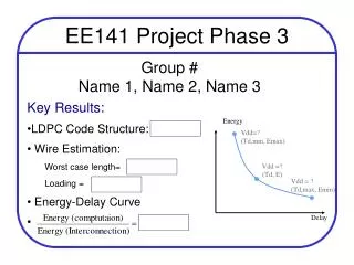
* * * Digital Circuit Design Considerations • Functionality • Design logic correctly • Increase noise margin and reduce noise • Area • Minimize gate / device count • Do compact layout • Speed • Optimizations on circuit structure, sizing and Vdd … • Power • Minimize the area • Optimizations on sizing and Vdd
Logic Graph & Euler Path • Logic Graph and Euler path are effective tools in CMOS logic design and layout implementation. (Pg. 319) Euler path: A – B – C Example of logic graph
Stick Diagram Euler path: A – B – C
A Previous CMOS Design HW Problem Problem: Design the NMOS pull down network from the PMOS pull up network • There are actually multiple approaches to solve this problem
NMOS PDN function can be derived: • A Safe but messy approach Solution 1 — Logic Computation Observed for PMOS PUN:
NMOS PDN function can be derived easily: • More intuitional but be careful in it Solution 2 — Reverse the PMOS • Find those input patterns which block the PMOS paths from Vdd to F: • AB, CD, AED, BEC
Very effective help-out with this tool • Unfortunately this logic graph doesn’t have a Euler path. Thus just practice with your hw prob. Then. Solution 3 — Logic Graph
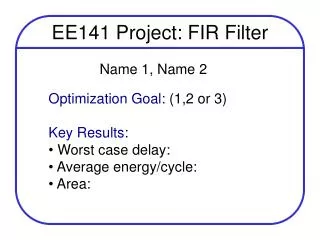
Project 1 — Clock Driver Design • There do exist a optimum sizing point for each group as the reference result. • But there is no ‘standard’ method or equation leading to this result. — Those are for homework or exam, not for project. • As long as your optimization result is close to the optimum point, and you support it with clear methodology based on design considerations and analysis, you are in good shape. • Actually you should be able to tell in the end whether you get it or not, since you should have understood all the trade offs in the design well if you are doing the right analysis.
Project 1 — Grading Criteria • The correctness of your result (is it close to the optimum point?) • Your methodology behind the result (make it logical and CLEAR) • The quality of your report (present your work nicely) • Start working on the report EARLY. Don’t wrap it up 2 hours before the project due. That’ll hurt your effort.
An Effective Approach • No matter how complicated the problem is, start from something simple, and then increase your understanding on the whole system, step by step. • Any engineering work is based on a simplified model of the reality. But building the model sometimes requires more expertise than solving it. • You can’t get everything done in one strike. Don’t try to model the whole system with one equation or equation group. • Identify those dominant factors and attack them, then check those others.
y z x Project — Delay Minimization • Why we want to increase the size of buffers geometrically? • tp (y) = tp0 (1+y/xγ) + tp0 (1+z/yγ) + … • To minimized tp by sizing the middle inverter — • Conclusion: geometric sizing minimizes buffer chain delay!
Delay → Delay ↓ Delay ↑ Project — Energy optimization • Why happens with energy optimization? 0.8*x2 • Obviously the gate with the largest size deserves an attack — • If its size is reduced by 20%, the total energy reduction ~ 20% • Delay of this final stage increase by less than 25%. Delay of the • middle stage decreases. Thus the overall delay should increase by • less than 8%. • Then how about the sizing of stages before the last one? • And what if we optimize the Vdd at the same time?