Download
1 / 40
400 likes | 472 Vues
Wireless Item Label Locator (WILL). The Third Eye Ltd. Tongxin Feng, CEO Jieun Choi, VPRD Sieun Lee, VPRD April 21, 2008. ENSC 440 Project Presentation/Demo. Presentation Outline. Introduce the Team Why WILL? : Project Background & Motivation System Overview & High Level System Design

E N D
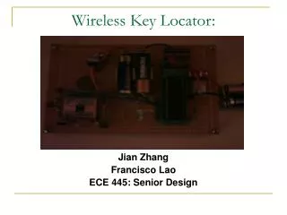
Wireless Item Label Locator(WILL) The Third Eye Ltd. Tongxin Feng, CEO Jieun Choi, VPRD Sieun Lee, VPRD April 21, 2008 ENSC 440 Project Presentation/Demo
Presentation Outline • Introduce the Team • Why WILL? : Project Background & Motivation • System Overview & High Level System Design • Business Case • Project Specifics • Lesson Learned • Conclusion & Future Works • Sources & Acknowledgements • Questions & Some System Details
The Third Eye Team • Tongxin Feng (President/CEO) • 5th year Electronics Engineering • MC Programming / User Interface Design & Construction • Tasks & Schedule Management • Jieun Choi (VP Research & Development) • 6th year Systems Engineering • Overall RFID research / Reader – MC Communication & Programming / User Interface Design & Construction • Resource & Budget Management • Sieun Lee (VP Research & Development) • 6th year Engineering Physics • Antenna Modification and Performance Test / Reader – MC Support / Power Supply and Delay Unit Design & Construction • Documentation Management
Why WILL? • Motivation How much time do I spend searching for my key/wallet/cell phone/etc. in my room? How difficult would it be for a blind person to find a misplaced item? The leading cause of blindness is aging – which often comes with memory loss as well. • Further User & Market Research There is a need/want, but no satisfying product. The Problem: Tag Battery Life
System Overview • What WILL does • Features • Intuitive user interface, direction/range detection • Tags do not require batteries • Portable
System Overview • Design Overview
Reader Module Microcontroller Protocol Communication Reader communication Antenna User interface High-Level System Design (J) • Reader and Microcontroller module Reader Protocol TTL TTL request response request response request request response
High-Level System Design (J) • User Interface and Microcontroller User Interface Microcontroller Button 1 User Interface Request Reader Comm Button 2 Button 3 LED Response Buzzer
User Interface Braille
Antenna • Linearly polarized, UHF monopole antenna • Problems i) Polarization & Directionality ii) Size • Why still this antenna? • Most marketed directional antennas are large, especially in UHF range. Most RFID devices are omni-directional. • Must design & build an antenna - time and budget constraints • How we compensated • Somewhat directional – strongest signal in the direction of the tag • Add a parabolic dish and metal back plate for better gain & directionality. (Bigger size though)
Business Case • Market • 19.7 million in North America with visual impairment • Item locating function also marketable to healthy population • Cost • Active tags are around $10 -$ 50 dollars. But for each tag, users require to change battery from 1 month to 6 months depends on how much they use • WILL costs around $350 and need rechargeable batteries for the reader. • UHF reader and antenna are expensive, so instead lowering the cost, expanding the feature such as UHF RFID home security can be an option.
Business Case • Financing • Investors • International funding sources to develop assistive devices • Competition • Other assistive devices for the visually impaired (Direct/indirect) • RFID products
Time Line Expectation Actual time
Lesson Learned • Not to overload oneself • Do ample research before choosing a project - simplest ideas can be the most difficult to implement • If you run into a problem, it is highly possible someone else run into the same problem • Even if you don’t seem to progress, you are actually learning
Conclusion • We were able to achieve the significant part of the two important functions that were proposed only for the product stage : indicating the direction and relative range of the tag!
Future Works • Design and build a small, directional antenna • Make more user friendly interface using speaker to let user know the stage of the process and use lock in buttons • Build more stable circuit for power module and user interface • Reduce the size and the increase the battery life
Sources & Acknowledgement • Dr. Patrick Leung and Steve Whitmore, Instructors • Brad Oldham and Jason Lee, TAs • Fred Heep and Marius Haiduku, Lab Technicians • Dr. Rodney Vaughn, Dr. Shawn Stapleton and Jane Yun, RF/Microwave Mobile Communication Laboratory • Derek Pyner, Pacific Design Engineering • Andrey Gleener, Andrey Gleener R&D Services
Demo • Item 1
Demo • Item2
Demo • Item3
Extension • Why did we need one month extension? • Looking for parts – 2 weeks delay Late January and early February, we were not able to find the right UHF RFID development product. • Required long range but small size product • Fully assembled products – therefore, not much room for development and mostly software development was encouraged for UHF • No schematic or source code provided • Reader and Microcontroller connection – 1 month delay
Reader Module Connection • Problem 1 – Late February until early March Reader module cannot be program at all except changing some settings; therefore, we were not able to control the reader module directly • Problem 2 – Early March until end of April Reader module and Microcontroller cannot communicate to each other using UART or TTL signals
RS232 RS232 Reader module on interface board Microcontroller on interface board Computer Reader Module Connection • Trial 1 : Connect each module separately to computer using RS232 signals • Result: Both modules communicate successfully
Null modem Cable Reader module on interface board Microcontroller on interface board Reader Module Connection • Trial2: Connect reader module and MC together using RS232 signals via null modem cable • Result: auto shutdown occurred
Reader Module Connection • Null Modem Cable • RS232 • DCE-DCE • How about Direct Connection? Auto shutdown did not occur however, the signals are not delivered • Auto shutdown • The level shifter chips believe that the input signals on both side Possible problem occurred due to level shifter chips, so we decided to use TTL signal directly
Reader module MC TTL Reader Module Connection • Trial 3: Connect Two module using TTL Signal • Result : no response occurred Signals may not be correct
Reader Module Connection • Checked TTL Signals on both side • Microcontroller • It seems like a proper signal as mentioned in data sheet • Reader module • It is not a correct signal as mentioned in data sheet ( Low: ~0V High:~4.5V) Reader module seems to cause a problem (later, we found out oscilloscope is very senstive to this reader module signals)
Reader module MAX232N TTL RS232 Reader Module Connection • Trial 4 : Generate TTL signal from the Computer RS232 signal • Because RS232 signals from computer transmits correctly to the reader module, we used MAX232N chips to convert RS232 signals back to TTL signal and feed into Reader module and see what happens • Result: No response
TTL MAX232N RS232 RS232 Input signal loop backs to output signal Reader Module Connection • Continued from Trial4 • Used Loop back system to see whether the signals from MAX232N chips is distorted • Result : Correct. Input and output are the same No problem in the signals from the chip. Reader module only understands the RS232 signals from computer but anything else
MC on interface board MC MAX 232N MAX 232N Reader Module Connection • Reader module communication trials All methods did not work RS232 Reader on interface board RS232 MC Reader TTL TTL
Reader Module Connection -Solved • How did we solve this problem? Check all the basics! After we used the right handshaking and all the right settings one of the setting was not fixed correctly. The MC stop bit was set as 2 bits where the reader module is set default to 1 bit. Until mid April, the setting was correct, however, it was changed during our trials, and we did not double check this setting later. We found it using logic analyzer.
Problems confronted • Power supply generates noise in Microcontroller TTL signals • Not enough time to investigate circuit. • We believe the problem occurred from input and output devices connected the Vcc. • Why are they connected to Vcc? We used the STK500 development board and to make it work without the development board, we used STK500 schematic to make the hardware environment as similar to do debugging