Download
1 / 18
180 likes | 300 Vues
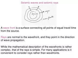
Imaging seismic waves from space. R émi Michel 1,2 , Sébastien Leprince 1 , Serge Primet 3 , S. Somala 1 , Jean-Paul Ampuero 1 , Nadia Lapusta 1 , Jean-Philippe Avouac 1. 1 California Institute of Technology, Pasadena, USA 2 Commissariat a l’Energie Atomique , Saclay , France

E N D
Imaging seismic waves from space • Rémi Michel1,2, Sébastien Leprince1, Serge Primet3, S. Somala1, Jean-Paul Ampuero1, Nadia Lapusta1, Jean-Philippe Avouac1 1 California Institute of Technology, Pasadena, USA 2 Commissariat a l’EnergieAtomique, Saclay, France 3 Institutd’Optique, Palaiseau, France
Motivation Source Model of the 1999, Mw 7.1 Duzce Earthquake. Data: SPOT offsets, inSAR, GPS, Seismograms (Konca et al, BSSA, 2010)
Motivation (Konca et al, BSSA, 2010) Source Model of the 1999, Mw 7.1 Duzce Earthquake: An initial crack-like rupture which evolve into a super-shear pulse
Motivation • Simulation of a seismic rupture: horizontal strike-parallel component of the velocity field), computed for a theoretical Mw 7.0 earthquake simulated using a rate&state friction law and the Spectral Element Method (e.g., Kaneko, Lapusta and Ampuero, 2009) t=15s 50km
Motivation • The determination of a kinematic source model from the inversion of static ground displacement and seismograms measured at a sparse set of seismic stations is an ill-posed problem. • …but such models are needed to investigate Earthquake physics.
Requirements 50km Mw7 -0.1 S-1 0.1 Mw6
Airborne/Space Systems A Large Geostationary Optical Telescope?
Photometry Essentials Wavelength (mm) Atmospheric Turbulence Wavelength (mm) Wavelength (mm) Ground Reflectance Sun Radiance Atmosphere Transmittance L:radiance, r: reflectance, S : atmosphere spherical reflectance Movie [0.4-2.5mm]
Horizontal offsetsMeasured by Correlation or Optical Flow 1/100 of the pixel size. SNR 1000 (reflectance 0.15, back-illuminated CCD) : 0.03 s per frame for f 4m. Stability is an issue for data management and not for accuracy.
Photoclinometry • Photoclinometry • Accuracy possible up to [10-4-10-5] (number of detected photons [1010 – 1011]) • r=0.15, pixel size : 100m, integration time 0.03s, most unfavorable incidence angle # 11 degrees
Simulations-Horizontal offsets Synthetic Mw 7.1, t=15s Telescope f10.m Telescope f4.0m Mw 6.0 t=4.22s Mw 6.0 t=4.22s Mw 6.0 t=4.22s Model (Mw 7.1, 30s, 2Hz, pixel:100m) and 2 critical telescope diameters (1Hz, pixel:100m)
Simulations-Horizontal offsets Telescope f10.0m Telescope f4.0m -0.1 S-1 0.1 Accuracy 1/50th pixel
f7.0m f4.0m Modele f10.0m
Simulations-Photoclinometry 0.004 rad.s-1 Synthetic (Mw7) Simulation (4m)
A Accuracy of Optical Correlation = f(f telescope, geostationary) A’ Transect • Model of strike slip fault (Mw 7.1), Field of view 60*24km, 1Hz, ground resolution 100m f4.0m Ariane V Compatible Horizontal Velocities [-0.4,+1.9] (m.s-1) A Model f10.0m f7.0m f4.0m f7.0m Challenging A’ f10.0m Challenging