Download
1 / 49
520 likes | 896 Vues
Photovoltaic Devices. Fall 2008 University of South Alabama. Outlines. Solar energy spectrum Photovoltaic device principles I-V Characteristics. Solar Energy Spectrum. Photovoltaic devices (solar cells) convert the incident solar radiation energy into electrical energy.

E N D
Photovoltaic Devices Fall 2008 University of South Alabama
Outlines • Solar energy spectrum • Photovoltaic device principles • I-V Characteristics
Solar Energy Spectrum • Photovoltaic devices (solar cells) convert the incident solar radiation energy into electrical energy. • Absorbed photons photogeneration current (photocurrent) in external cicuit. • Power range: from < mW (calculator) to few MW (photovoltaic power generation)
Solar Energy Spectrum • Spectral intensity Iλ: Intensity per wavelength. • Iλδλ: intensity in a small interval δλ. • Total intensity I: integration of Iλ over the whole spectrum. • Solar constant or air-mass zero (AM0): the total intensity above earth’s atmosphere, approximately constant at 1.353 kW m-2.
Solar Energy Spectrum • On sunny day, light intensity on earth’s surface is about 70% of the intensity above the atmosphere. • Absorption and scattering effects increase with the sun beam’s path through the atmosphere. • The shortest path through the atmosphere is when the sun is directly above that location and the received spectrum is called air mass one (AM1). • Air massm (AMm): the ratio of the actual radiation path h to the shortest path h0, m = h/h0. • Since h = h0secθ, AMm is AMsecθ.
Solar Energy Spectrum • The spectral distribution AM1.5 has several sharp absorption peaks at certain wavelengths which are due to those wavelength being absorbed by various molecule in the atmosphere, such as ozone, air, and water vapor molecules. • Dust particles scatter the sun light reduces the intensity and gives rise to the sun’s rays arriving at random angle.
Solar Energy Spectrum • Thus, the terrestrial light has a diffuse component in addition to direct component. • Cloud and sun position increase diffuse component spectrum shifted toward the blue light. • Scattering also increase with decreasing wavelength. • On a clear day, diffusion component can be about 20% of the total radiation. • The amount of incident radiation depends on the position of the sun. Photovoltaic device flat will receive less solar energy by factor cosθ However it can be tilted to directly face the sun to maximize the collection efficiency.
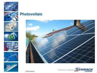
PV Cells have efficiencies approaching 21.5% Florida Solar Energy Center
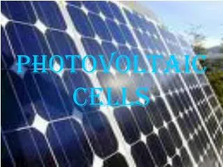
Silicon Solar Cell http://en.wikipedia.org/wiki/Image:Solar_cell.png
PV Modules have efficiencies approaching 17% Florida Solar Energy Center
Solar Panel Solar panel by BP Solar at a German autobahn bridge http://en.wikipedia.org/wiki/Solar_panel
International Space Station Hubble Telescope Mars Rover Spacecraft
Cross Section of PV Cell http://en.wikipedia.org/wiki/Solar_cells
Photovoltaic Device Principles • Consider pn+ junction with very narrow n-region. • The illumination is through then thin n-side. • The SCL extend mainly in p-region with built-in field E0. • Electrode at n-side must allow illumination to enter the device and at the same time result in a small series resistance. • This electrode is formed from array of finger electrodes.
Photovoltaic Device Principles • Photons are absorbed in SCL within the neutral p-side (lp) photogenerated EHP in this region. • The electron drifts and reaches the neutral n+ side whereupon it makes this region negative by an amount of charge –e. • Similarly, hole drifts and reaches the neutral p-side and thereby makes this side positive open circuit voltage between terminals of the device. • If there is external load, electron will travel through it and recombine with the excess holes in p-side.
Photovoltaic Device Principles • Therefore the existence of built-in field E0 is important to create accumulated electrons in the n-side and holes in the p-side. • For long wavelength photons absorbed in the neutral p-side no E field diffusion. • Minority carrier diffusion length Le. • τe: recombination lifetime of electron. • De: diffusion coefficient in the p-side.
Role of Diffusion Length • Only those EHPs photogenerated within the Le to the depletion layer can contribute to the photovoltaic effect. • Those photogenerated EHPs further away from SCL than Le are lost by recombination. • Thus, it is important to have the minority carrier diffusion length Le as long as possible. By choosing Si pn junction to be p-type which makes electrons to be minority carriers; the electron diffuse length in Si > the hole diffusion length.
Role of hole diffusion length and short circuit current • For EHPs photogenerated by short-wavelength photons absorbed in the n-side, within diffusion length Lh, can reach SCL and swept across to the p-side. • The photogenerated of EHPs that contribute to the photovoltaic effect occurs in a volume of absorption coefficient Lh + W + Le. • If the terminals are shorted then the excess electrons in the n-side can flow through the external circuit to neutralize the excess holes in the p-side this current is called photocurrent.
Photovoltaic Device Principles • Under steady state operation no net current through an open circuit solar cell Photocurrent inside the device due to photo generated carriers must be balanced by a flow of carriers in the opposite direction. • Those are minority carriers that become injected by the appearance of the photovoltaic voltage across the pn junction as in normal diode.
Device optimization and carrier losses • For long wavelengths, 1 – 1.2 μm, α is small absorption depth 1/α is typically greater than 100 μm. Need a thick p-side and long minority carrier diffusion length Le. • Thus, p-side is 200 – 500 μm and Le is shorter than that. • Si has Eg = 1.1 eV correspond to a threshold wavelength of 1.1 μm The incident energy with wavelength > 1.1μm is then wasted (~ 25%). • Photons are absorbed and recombined near the crystal surface losses. absorption coefficient
Sources of carrier losses • Photons are absorbed and recombined near the crystal surface losses severely reduce efficiency. • Crystal surface and interface contain high concentration of recombination-center. • Those facilitate the recombination of photogenerated EHP near the surface. • The losses due to this event as high as ~ 40%. • These combined effect bring the efficiency down to about 45%. • Antireflection coating is also contributing the reduction of photons collection due to imprefection with factor of 0.8 – 0.9. • And including the limitation of photovoltaic action the upper limit to a photovoltaic device that uses single crystal of Si is about 24 – 26% at room temperature.
pn Junction Photovoltaic I-V Characteristics • Consider an ideal pn junction photovoltaic device connected to a resistive load R. • I and V define the convention for the direction of positive current and positive voltage. • If the load is short circuit the only current in the circuit is due to photogenerated (photocurrent),Iph.
pn Junction Photovoltaic I-V Characteristics K is constant that depends on particular device • If I is the light intensity, then the short circuit current is • The photocurrent does not depend on the voltage across the pn jucntion, because it always some internal field to drift the photogenerated EHP. • If R is not short circuit the positive voltage V appears across the pn junction as a result of the current passing through.
pn Junction Photovoltaic I-V Characteristics • The voltage across the load R (with opposite polarity) reduces the built in potential V0 of the pn junction and hence leads to minority carrier injection and diffusion. • Thus, in addition to Iph there is also a forward diode current Id in the circuit which arises from the voltage developed across R. • Since Id is due to the normal pn junction behavior diode characteristics, • where I0 is the reverse saturation current, n is the ideality factor which depends on semiconductor material and fabrication chaeacteristics (n = 1 – 2).
pn Junction Photovoltaic I-V Characteristics • Thus, the total current (solar cell current), • The I-V characteristics of a typical Si solar cell (Fig.). • Normal dark characteristics being shifted down by photocurrent Iph (short circuit), which depend on light intensity, I. • The open circuit voltage, Voc, is given by the point where the I-V curve cuts the V-axis (I = 0).
pn Junction Photovoltaic I-V Characteristics • The I-V curves for positive current requires an external bias voltage. • Although Voc depends on the light intensity, it value lies between 0.4 – 0.6 V. • Photovoltaic operation is always in the negative current region. • Thus the load line,
pn Junction Photovoltaic I-V Characteristics • When a solar cell drives a load R, R has the same voltage as the solar cell but the current through it is in the opposite direction to the convention that current flows from high to low potential. • The current I’ and voltage V’ can be found by solving two previous equations simultaneously not trivial analytical procedure.
Photovoltaic I-V Characteristics (load line analysis) • Or they can be found easily from load line construction. • The load line cuts the solar cell characteristics at P. Point P satisfies both equations represent the operating point of the circuit.
Maximum power and fill factor • The power delivered to the load is Pout = I’V’ the area bound by I- and V-axes and the dashed lines. • Maximum power delivered by changing R max area when I’ = Im and V’ = Vm. • The fill factor FF, FF range is 70 – 80% FF is a measure of the closeness of the solar cell I-V curve to the rectangular shape
Series Resistance and Equivalent Circuit • Practical devices ≠ ideal pn junction device. • Photogenerated electron has to transverse a surface semiconductor region to reach the nearest finger electrode create an effective series resistance Rs.
Series Resistance and Equivalent Circuit • Equivalent circuit of an ideal pn junction solar is represented by a constant current generator Iph. • The flow of photogenerated carriers across the junction gives rise to a photovoltaic voltage V. This voltage leads to a normal diode current Id = I0[exp(eV/nkBT)-1] Id is represented by and ideal pn junction diode. • Iph and Id are in opposite directions open circuit the photovoltaic voltage is such that Iph and Id have the same magnitude and cancel each other.
Series Resistance and Equivalent Circuit • Equivalent circuit for practical solar cell include series resistance Rs gives rise to a voltage drop. • Photogenerated carriers can also flow through the crystal surfaces or grain boundaries in polycrystalline devices, instead of flowing through the external load RL represented by an effective internal shunt or parallel resistance Rp. • Typically Rp is less important than Rs unless the device is highly polycrystalline.
Series Resistance and Equivalent Circuit • Series resistance Rs can significantly deteriorate the cell performance. The max power decrease reduce cell efficiency.
Temperature Effects • Temperature decreases Output voltage and efficiency increase. • Solar cell operate best at lower temperature. • The output voltage Voc, when Voc >> nkBT/e, • I0 is reverse saturation current and strongly depend on temperature, because it depends on square of ni. • If I is light intensity,
Temperature Effects • Assuming n = 1, at two different temperatures T1 and T2 but the same illumination level, by subtraction, • Substitute, • Thus, • Rearrange for Voc2,
Temperature Effects • Example, Si solar cell has Voc1 = 0.55 V at 20 oC (T1 = 293 K), at 60 oC (T2 = 333 K),
Solar Cells Materials, Devices and Efficiencies • For a given solar spectrum, conversion efficiency depends on the semiconductor material properties and the device structure. • Si based solar cell efficiencies 18% for polycrystalline and 22 – 24% for single crystal devices. • About 25% solar energy is wasted not enough energy unable to generate EHPs. • Considering all losses, the maximum electrical output power is ~20% for a high efficiency Si solar cell.
Solar Cells Materials, Devices and Efficiencies • Si homojunction solar cell efficiencies ~24%. Single crystal PERL (Passivated Emitter Rear Locally-diffused) cells.
Solar Cells Materials, Devices and Efficiencies • Semiconductor alloy III-V different bandgap with the same lattice constant Heterojunction.
Solar Cells Materials, Devices and Efficiencies • Example n-AlGaAs with p-GaAs.
Solar Cells Materials, Devices and Efficiencies • To further increase the absorbed photons tandem or cascade cells (use two or more cells in tandem), such as GaAs – GaSb.