Download
1 / 48
480 likes | 676 Vues
Applied Magnetism. Wang C. Ng Sep. 21, 2009 wang.ng@scc.losrios.edu (916)558-2638. References:. http://hyperphysics.phy-astr.gsu.edu/hbase/hframe.html ; 9-13-2009. http://www.magnet.fsu.edu/ ; 9-13-2009. http://www.hobbyprojects.com/components/inductors.html ; 9-13-2009.

E N D
Applied Magnetism Wang C. Ng Sep. 21, 2009 wang.ng@scc.losrios.edu (916)558-2638
References: • http://hyperphysics.phy-astr.gsu.edu/hbase/hframe.html; 9-13-2009. • http://www.magnet.fsu.edu/; 9-13-2009. • http://www.hobbyprojects.com/components/inductors.html; 9-13-2009. • http://www.electronicsteacher.com/electronics-dictionary/electronics-dictionary-f.php; 9-14-2009. • J.J.Cathey & S.A.Nasar; Basic Electrical Engineering; McGraw-Hill, NY, 1984.
Magnetic Properties of Solids • Materials may be classified by their response to externally applied magnetic fields as diamagnetic, paramagnetic, or ferromagnetic. • These magnetic responses differ greatly in strength. • Diamagnetism is a property of all materials and opposes applied magnetic fields, but is very weak.
Magnetic Properties of Solids • Paramagnetism is stronger than diamagnetism and produces magnetization in the direction of the applied field, and proportional to the applied field. • Ferromagnetic effects are very large, producing magnetizations sometimes orders of magnitude greater than the applied field and as such are much larger than either diamagnetic or paramagnetic effects.
Magnetization • The magnetization of a material is expressed in terms of density of net magnetic dipole momentsm in the material. • We define a vector quantity called the magnetization M = μtotal/Volume. • The total magnetic fieldB in the material is given by B = B0 + μ0M where μ0 is the magnetic permeability of space and B0 is the externally applied magnetic field.
Magnetization • Another way to view the magnetic fields which arise from magnetization of materials is to introduce a quantity called magnetic field strength H . • It can be defined by the relationship H = B0/μ0 = B/μ0 – M • H has the value of unambiguously designating the driving magnetic influence from external currents in a material, independent of the material's magnetic response.
Magnetization • H and M have the same units, amperes/meter. • The relationship for B and H above can be written in the equivalent form B = μ0 (H + M) = μr μ0 H, where μr = (1 + M/H) • The relative permeability mr can be viewed as the amplification factor for the internal field B due to an external field H.
Diamagnetism • The orbital motion of electrons creates tiny atomic current loops, which produce magnetic fields. • When an external magnetic field is applied to a material, these current loops will tend to align in such a way as to oppose the applied field. • This may be viewed as an atomic version of Lenz's law: induced magnetic fields tend to oppose the change which created them. Materials in which this effect is the only magnetic response are called diamagnetic.
Diamagnetism • All materials are inherently diamagnetic, but if the atoms have some net magnetic moment as in paramagnetic materials or in ferromagnetic materials, these stronger effects are always dominant. • Diamagnetism is the residual magnetic behavior when materials are neither paramagnetic nor ferromagnetic.
Diamagnetism • Any conductor will show a strong diamagnetic effect in the presence of changing magnetic fields because circulating currents will be generated in the conductor to oppose the magnetic field changes. • A superconductor will be a perfect diamagnet since there is no resistance to the forming of the current loops.
Paramagnetism • Some materials exhibit a magnetization which is proportional to the applied magnetic field in which the material is placed. • These materials are said to be paramagnetic and follow Curie's law:
Paramagnetism • All atoms have inherent sources of magnetism because electron spin contributes a magnetic moment and electron orbits act as current loops which produce a magnetic field. • In most materials the magnetic moments of the electrons cancel, but in materials which are classified as paramagnetic, the cancelation is incomplete.
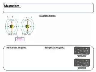
Ferromagnetism • Iron, nickel, cobalt and some of the rare earths (gadolinium, dysprosium) exhibit a unique magnetic behavior which is called ferromagnetism because iron (ferrum in Latin) is the most common and most dramatic example. • Samarium and neodymium in alloys with cobalt have been used to fabricate very strong rare-earth magnets.
Ferromagnetism • Ferromagnetic materials exhibit a long-range ordering phenomenon at the atomic level which causes the unpaired electron spins to line up parallel with each other in a region called a domain. • Within the domain, the magnetic field is intense, but in a bulk sample the material will usually be unmagnetized because the many domains will themselves be randomly oriented with respect to one another.
Ferromagnetism • Ferromagnetism manifests itself in the fact that a small externally imposed magnetic field, say from a solenoid, can cause the magnetic domains to line up with each other and the material is said to be magnetized. • The driving magnetic field will then be increased by a large factor which is usually expressed as a relative permeability for the material.
Ferromagnetism • There are many applications of ferromagnetic materials, such as the electromagnet. • Ferromagnets will tend to stay magnetized to some extent after being subjected to an external magnetic field. • This tendency to "remember their magnetic history" is called hysteresis. • The fraction of the saturation magnetization which is retained when the driving field is removed is called the remanence of the material, and is an important factor in permanent magnets.
Ferromagnetism Hysteresis
Ferromagnetism • All ferromagnets have a maximum temperature where the ferromagnetic property disappears as a result of thermal agitation. • This temperature is called the Curie temperature. • Ferromagntic materials respond mechanically to an impressed magnetic field, changing length slightly in the direction of the applied field. • This property, called magnetostriction, leads to the familiar hum of transformers as they respond mechanically to 60 Hz AC voltages.
Inductance (review) • Increasing current in a coil of wire will generate a counter emf which opposes the current. • Applying the voltage law allows us to see the effect of this emf on the circuit equation. • The fact that the emf always opposes the change in current is an example of Lenz's law. • The relation of this counter emf to the current is the origin of the concept of inductance. • The inductance of a coil follows from Faraday's law.
Inductance (review) • Inductance of a coil: For a fixed area and changing current, Faraday's law becomes • Since the magnetic field of a solenoid is then for a long coil the emf is approximated by
Inductance (review) • From the definition of inductance we obtain
Relative Permeability • The magnetic constant μ0 = 4π x 10-7 T m/A is called the permeability of space. • The permeabilities of most materials are very close to μ0 since most materials will be classified as either paramagnetic or diamagnetic.
Relative Permeability • But in ferromagnetic materials the permeability may be very large • It is convenient to characterize the materials by a relative permeability.
Relative Permeability • When ferromagnetic materials are used in applications like an iron-core solenoid, the relative permeability gives you an idea of the kind of multiplication of the applied magnetic field that can be achieved by having the ferromagnetic core present. • For an ordinary iron core you might expect a magnification of about 200 compared to the magnetic field produced by the solenoid current with just an air core.
Relative Permeability • This statement has exceptions and limits, since you do reach a saturation magnetization of the iron core quickly, as illustrated in the discussion of hysteresis.
Eddy Currents • Currents that are induced into a conducting core due to the changing magnetic field. • Eddy currents produce heat which results a loss of power • This effect can reduce the efficiency of an inductor or a transformer. • The Eddy current loss is proportional to f 2. http://www.magnet.fsu.edu/education/tutorials/slideshows/eddycurrents/index.html
Ferrites • Compound composed of iron oxide, metallic oxide, and ceramic. • The metal oxides include zinc, nickel, cobalt or iron. • A powdered, compressed and sintered magnetic material having high resistivity. • The high resistance makes eddy current losses low at high frequencies.
Ferrites vs. iron cores • Iron cores are used for frequencies below about 100 kHz. • Ferrite cores are used for frequencies up to say, 10 MHz. • Above 100MHz the core is usually air and the coil is self supporting.
Ferrites vs. iron cores • At low frequencies the inductor may have hundreds of turns, above 1 MHz only a few turns. • Most inductors have a low DC resistance since they are wound from copper wire.
Inductance of a Solenoid http://hyperphysics.phy-astr.gsu.edu/hbase/electric/indsol.html#c1
Inductance of a Solenoid Solenoid length = 10 cm with N = 200 turns, Coil radius r = 1 cm gives area A = 3.14159 cm2. Relative permeability of the core k = 200, Then the inductance of the solenoid is L = 31.58 mH.
Inductance of a Solenoid • Small inductors for electronics use may be made with air cores. • For larger values of inductance and for transformers, iron is used as a core material. • The relative permeability of magnetic iron is around 200. • This calculation makes use of the long solenoid approximation.
Approximate Inductance of a Toroid http://hyperphysics.phy-astr.gsu.edu/hbase/magnetic/indtor.html#c1 • Finding the magnetic field inside a toroid is a good example of the power of Ampere's law. • The current enclosed by the dashed line is just the number of loops times the current in each loop.
Approximate Inductance of a Toroid • Amperes law then gives the magnetic field at the centerline of the toroid as
Approximate Inductance of a Toroid • The inductance can be calculated in a manner similar to that for any coil of wire.
Approximate Inductance of a Toroid Toroidal radius r = 5 cm with N = 200 turns, Coil radius = 1 cm gives area A = 3.14159 cm2. Relative permeability of the core k = 200, Then the inductance of the toroid is approximately L = 10.053 mH.
Approximate Inductance of a Toroid • Small inductors for electronics use may be made with air cores. • For larger values of inductance and for transformers, iron is used as a core material. • The relative permeability of magnetic iron is around 200.
Approximate Inductance of a Toroid • This calculation is approximate because the magnetic field changes with the radius from the centerline of the toroid. • Using the centerline value for magnetic field as an average introduces an error which is small if the toroid radius is much larger than the coil radius.
Transformer • A transformer makes use of Faraday's law and the ferromagnetic properties of an iron core to efficiently raise or lower AC voltages. • A transformer cannot increase power so that if the voltage is raised, the current is proportionally lowered and vice versa.
Magnetic Circuits http://www.magnet.fsu.edu/education/tutorials/java/magneticshunt/index.html • A magnetic circuit is a path for magnetic flux, just as an electric circuit provides a path for the flow of electric current. • Transformers, electric machines, and numerous other electromechanical devices utilize magnetic circuits. • If the magnetic field B is uniform over a surface A and is everywhere perpendicular to the surface the magnetic flux = B A.
Magnetic Circuits • The effectiveness of electric current in producing magnetic flux is defined as the magnetomotive force = N I. • The reluctance of a magnetic circuit is defined as: = / • Ohm’s law: R = V / I R = l / A = = l / μ A
Magnetic Circuits • Differences between a resistive circuit and a magnetic circuit: • There is I 2 R loss in a resistive circuit but no 2 loss in a reluctance. • Magnetic flux can leak to the surrounding space. • A magnetic circuit can have air gaps. • In general, the permeability μ is not a constant.
Magnetic Circuits • Mutual inductance: • (coupling coefficient) is defined as the fraction of the flux produced by the qth coil that links the pth coil. • 1 if fringing is negligible.
Magnetic Circuits • Finally, the self and mutual inductances can be computed from the following formula:
Magnetic Circuits Example: The core of a magnetic circuit is of mean length 40 cm and uniform cross-sectional area 4 cm2. The relative permeability of the core material is 1000. An air gap of 1 mm is cut in the core, and 1000 turns are wound on the core. Determine the inductance of the coil if fringing is negligible.