Download
1 / 89
1.56k likes | 2.81k Vues
OBJECT ORIENTED ANALYSIS AND DESIGN. OBJECT ORIENTED ANALYSIS AND DESIGN. OBJECT ORIENTED ANALYSIS - Identification of domain model OBJECT ORIENTED DESIGN - Construction of of domain model OBJECT ORIENTED PROGRAMMING - Implementation of domain model. UNIFIED MODELING LANGUAGE.

E N D
OBJECT ORIENTED ANALYSIS AND DESIGN OBJECT ORIENTED ANALYSIS -Identification of domain model OBJECT ORIENTED DESIGN -Construction of of domain model OBJECT ORIENTED PROGRAMMING -Implementation of domain model
UNIFIED MODELING LANGUAGE DEFINITION UML Defined as modeling language for specifying , constructing, visualizing and documenting the real world object or system OBJECTIVE To show visual representation of real world system
MODEL 1.Static Model-Describe the object structure 2.Dynamic Model-Describe the object collaboration
UML DIAGRAMS 1.Use case Diagram 2.Class Diagram 3.Sequence Diagram 4.Collaboration Diagram 5.Activity Diagram 6.State Chart Diagram 7.Component Diagram 8. Deployment Diagram
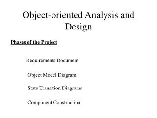
USECASE DIAGRAM CLASS DIAGRAM SEQUENCE DIAGRAM COLLABORATION DIAGRAM Requirement Documents USECASE ACTIVITY DIAGRAM STATE CHART DIAGRAM COMPONENT DIAGRAM DEPLOYMENT DIAGRAM
USECASE DIAGRAM USECASE-Usecase are functional Requirements. STEPS TO IDENTIFY THE USECASE: 1. Choose system boundary-define scope 2. Identify the actors 3. Identify the primary and secondary actors
4. Identify the goal of each actors Example: Goal of cashier-process a sale, cash in, cash out Goal of admin-add the user, modify the user, delete the user 5. Finally Identify usecase Example: Usecase of cashier-process sale Usecase of admin-add user, modify user, delete user.
USECASE DIAGRAM • Used to represent relationship b/w actor and usecase Add user Delete user Modify user
NOTATION FOR USECASE DIAGRAM • System boundary-define scope of system • Usecase-Functional Req that define what the system will do • Actors-Something with behavior Usecase Name S/m Boundary
RELATIONSHIP FOR USECASE DIAGRAM Usecase name 1.Association-Relationship b/w actor and usecase PAYMENT BY CASH PAYMENT BY CREDIT PAYMENT 2.Generalization-Relationship b/w most general and most specific usecase PAYMENT BY DEBIT
rg Scan item include 3.Include-Relationship b/w complex and simple usecase 4.Extend-Relationship b/w base and optional usecase include rg Calculate total CHECKOUT include payment rg Extend Order food Order Wine Extend Drink Wine Eat food Extend Pay for wine Pay for Food
System On USECASE DIAGRAM FOR ATM MACHINE System Off S/m Maintenance Verify Account Add Cash Include Maintain Customer Account Perform Transaction Bank Withdraw Get Balance Deposit
USECASE DIAGRAM FOR RESTAURENT MODEL jkl Receive order Extend Order Wine Order Food Conform order Serve food Cook Food Extend Drink Wine Eat Food Extend Serve Wine Receipt for payment Extend Pay for wine Pay for Food Accept Payment
UML CLASS DIAGRAM CLASS DIAGRAM: • Main objective is to define static structure of system • Used to represent set of class, Attributes, Operation, Interface, association, Multiplicity and Relationship. STEPS TO CREATE CLASS DIAGRAM: 1.Create Domain model-Visual Rep of Conceptual Classes -Find Conceptual Classes -Add attributes and Operation -Identify Association and Multiplicity 2. Redefine domain model-With class diagram relationship
CREATE DOMAIN MODEL UML Notation for Class Class Name Conceptual class-Collection of similar object Attributes-Logical data values List of Attributes List of Operation Class sample { Public int x=10; Public int y=20; Public int add() { Return(x+y); } Public static void Main() { Sample obj1=new sample(); Int s=obj1.add(); Console.writeline(“sum=“+s); } Syntax- visibility name attributes name: datatype
Transaction +Trans.Id:numeric +Trans.type:str +Trans.date:date +Trans.time:time +Trans.amount:float +Balance:float Customer +Fname:str +Lname:str +Add:str -Pinno:numeric Example for attributes: Account +Acc.no:numeric +Acc.type:str ATMMachine MachineId:numeric Address:str
Operation: Are events, Responsible for managing the value of attributes Syntax- Access modifier mathodname() Example: Customer +Verifyuser() Account +Deposit() +Withdraw() +Getbalance()
Class A Class B Association: Association Work For sam Company Employer Employee Binary Association OR Association ‘N’ Array Association
Contains House Furniture Binary Association: • OR Assocation: Company Work For Employee OR Work For Bank
Grandparent ‘N’ Array Association: Parent Person Child
One to One(1…1) Multiplicity- Range of association Multiplicity One to Many(1….*) Many to Many(*…..*) 1 1 Husband Wife 1 * Father Son * * Brother Sister
REDEFINE DOMAIN MODEL Association Aggregation Composition Generalization Dependency Relationship ASSOCIATION AGGREGATION COMPOSITION GENERALIZATION DEPENDENCY
Having Car Person Association: Aggregation: Team Player Player Player
Car 4 5,10 1 2,4 Composition: Generalization: Engine Wheel Light Door Vehicle Truck Bus Car
Dependence : Account Transaction TransID: Numaric TransDate: Date TransTime:Time TransAmount:Float CurrentBal:Float Account no: Number Account Type: String Depends On Balance: Float Withdraw() Deposit() BalanceEnq() GetTransHistory()
AtmMachine Address:str State:str Bank DOMAIN MODEL FOR BANKING SYSTEM Customer Fname:str Lname:str Pinno:numeric VerifyUser() Account Acc.no:str Balance:float Deposit() Withdraw() Getbalane() Transaction TransId:str TransDate:date TransTime:time TransType:str TransAmount:float 1 has 1,2 1 Has * SavingAccount Acc.Type:saving CheckingAccount Acc.type:Checking
Procuct Description ItemPrice ItemId GetPrice SaleLineItem Itemname:str Itemid:numeric Quantity:numeric Price:float GetSubTotal() Item ItemName:str ItemId:numeric Quantity:numeric Store Name:str Add:str Record sale of Stocked in Described-by DOMAIN MODEL FOR PROCESS SALE contain Payment Amount:float Sale Date:date Time:time GetTotal() Captured on Register Paid-by Cashpayment Amount DebitPayment DebitNo:numeric CreditPayment creditNo:numeric
UML INTERACTION DIAGRAM Used to describe how group of object collaborated to achieve goal UML Interaction diagram 1.Sequence diagram 2. collaboration diagram
SEQUENCE DIAGRAM • Used to describe how sequence of message exchange b/w two objects SEQUENCE DIAGRAM FOR TELEPHONE CALL Exchange :X :Y Lift the Receiver Receive Dial Tone Dial No Invalid No <Exception> Send Ring Tone Invalid No Lift the Receiver Object X and Y Exchange the Information
:User Lifeline Box BASIC NOTATION FOR SEQUENCE DIAGRAM: 1.Lifeline-represent scope 2. Lifeline Box-represent set of objects 3. Message-represent flow of events Lifeline :Y :X Message Name
:x 4.Message to self-object to itself 5. Object Destruction-remove object Message to Self -- :X :Y <Destroy>
6. Looping Cashier System Loop Enter Item(Item Id, Quantity) Display Description and Total
SEQUENCE DIAGRAM FOR PROCESS SALE Scenario for process sale: • Customer waiting for checkout with items • Cashier starts a new sale • System displays data entry sheet • Cashier enters item details • System records item and display item description, running cost • Cashier repeat the step 4&5 until complete the process • Once all the item have been entered ,the cashier end the sale • System display total cost with tax • Cashier request customer to pay the amount • Customer pays amount for item • Cashier handle payment • System dispatch receipt for payment • Cashier dispatch change& receipt to the customer
:Customer :Cashier :System Wait for Checkout Make new sale Data Entry Sheet Enter Item(Id, Quantity) Loop Description, Total End Sale Total Cost with Tax Request Payment Make Payment Handle Payment Dispatch Receipt Dispatch Change&Receipt Complete Process sale
COLLABORATION DIAGRAM • Used to represent object interaction in a n/w format Sequence of message :A Direction of data flow 1:message 1 • Association link 2:message 2 :B Message Name
Link Notation for collaboration diagram: Link- connection or navigation path b/w two object Message-Represent behavior of system :A :B 1.Enter name & pwd :User :Window 4:Valid User 2.Verify with DB :DB 3:Self Checking
1:WAIT FOR CHECK OUT 8:REQUEST PAYMENT :Customer :Cashier COLLABORATRION DIAGRAM FOR PROCESS SALE 12:DISPATCH CHANGE & RECEIPT 9:MAKE PAYMENT 2:MAKE NEW SALE 3:DATA SHEET 4:ENTERITEM(ID,QUANTITY) 5:DESCRIPTION AND COST 6:END SALE 7:TOTAL COST+TAX 10:HANDLE PAYMENT 11:DISPATCH RECEIPT :System
ACTIVITY DIAGRAM • Graphical representation of data flow from one activity to another activity • Commonly contain, 1.Action State- atomic state 2.Activity State- composite state 3.Transition- Represent direction of data flow 4.Branching-decesion making purpose 5.Fork –division purpose 6.Join-synchronization purpose
Simple Action Search Delete Action State- atomic state Activity State- composite state Transition- Represent direction of data flow Simple Action Calculate Percentage Calculate Total
Initial State Branching- decision making purpose Enter user name & pwd Action State Re-Enter Username & Pwd Verify Branching If Valid False Transition True Next Activity Final State
Fork and Join– division & synchronization purpose Select Pattern Fork Pattern1 Pattern2 Pattern3 Join View Score
ACTIVITY DIAGRAM FOR ONLINE QUIZ Get username and password No Invalid password verify Yes Select pattern Pattern1 Pattern2 Pattern3 Ans the questions Ans the questions Ans the questions View Score
Activity Diagram for telephone Call Lift Receiver receive Dial tone Redial No. Dial Number Is the No. Valid ? No Yes Yes Is the No. Busy? No Send Ring tone Is the User busy? Yes No Lift Receiver Connect C & R
STATECHART DIAGRAM • Graphical representation of object state, transition, event & action Initial State State Event Offhook IDLE ACTIVE Final State Onhook Transition
OBJECT STATE Object state- situation of object Name of the Component Idle Lift Receiver/Hear Dial Tone Internal Transaction Event Action or Activity
Object state types 1.Initial- Starting point of Execution 2.idle- Waiting for user command 3.active- Perform action response to event 4.final- Ending point of execution 5.Nested state
Transaction Key ON State Initial Idle Active Key OFF Final Event Nested State: Validate No No. Valid() Dial Idle Entry/No.append(n) Lift Receiver/Hear Dial Tone
TRANSITION Transition: Relationship b/w two object state when event occurs, object transition from one state to another state. Simple Transition Transition Complex Transition