Download
1 / 20
210 likes | 307 Vues
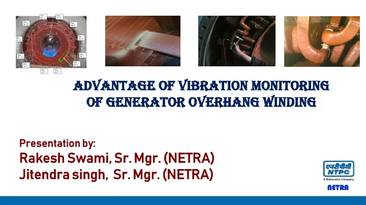
Advantage of vibration monitoring of generator overhang winding. Presentation by: Rakesh Swami, Sr. Mgr. (NETRA) Jitendra singh, Sr. Mgr. (NETRA). NETRA - R&D Wing of NTPC. Focus Areas Efficiency & Availability improvements New & Renewable Energy Climate Change, Environment & Waste Mgmt

E N D
Advantage of vibration monitoring of generator overhang winding Presentation by: Rakesh Swami, Sr. Mgr. (NETRA) Jitendra singh, Sr. Mgr. (NETRA)
NETRA - R&D Wing of NTPC Focus Areas Efficiency & Availability improvements New & Renewable Energy Climate Change, Environment & Waste Mgmt Advance Scientific Services Labs 11 Nos of NABL ISO 17025 accredited Test Lab 8 Nos of Advanced Process labs 140 types of analytical tests 140 type of specialized instrument Collaborations National – IITs, IISc, IGCAR, CSIR, ISRO, GSI, CIPET etc International –DLR, ISE, Curtin Univ, Newcastle Univ
Presentation Outline Overview 2 Causes of Failure 1 3 Testing Methodology Case Study 4 On line vibration monitoring 5 Major Facilities Added/To be Added Conclusion 6
Overview Causes of Failure Testing Methodology Major Facilities Added/To be Added Installed capacity of generators in power industries varies from few MW to 1000MW
Overview • Stator winding are double layer lap winding • Top and bottom bars are brazed to form a turn and several such turns form a phase • Phases are connected to form a double star winding • For making double star connection, 12 bars are used which are called main connecting bars • These bars are having more length and more extended portion at overhang due to which stiffness of these bars is less, hence these are more prone to high vibration Causes of Failure Testing Methodology Major Facilities Added/To be Added
Overview- End winding Support system • Stiffness of overhang winding is obtained by fixing these bars with supporting rings through packers and polyster chord • The supporting rings are welded together to form a cage. They transmit the mechanical forces to the outer casing . Causes of Failure Testing Methodology Major Facilities Added/To be Added
Overview • Mainly three types of generator cooling system are being used. • For small capacity of generator, air cooling system • For medium capacity i.e. 100 MW-210 MW, hydrogen cooling. • For higher capacity generators i.e. 500MW or more, hydrogen and water cooling system are in practice. • Some 210 MW capacity generators are also having hydrogen and water cooled system Causes of Failure Major Facilities Added/To be Added
Causes of Failure • The current in the stator winding produces a magnetic force which is proportional to square of the current • Magnetic force causing the coils to vibrate during operation at twice line frequency i.e. 100 Hz • After prolong operation of the machine, these vibrational stresses causing looseness of the overhang windings, which reduces the stiffness and change the natural frequency • Natural frequency of stator bar may reduce to near twice line frequency or line frequency, coinciding with frequency of electromagnetic force or line frequency which causes stator bar to vibrate in resonant condition • The high amplitude vibrations, cause relative motion and friction between insulation stator bars and stator core thus damaging the insulation and causing outage of the generator • To meet the grid requirement, load variations during operation result in thermal expansions and contractions, thereby subjecting the generator bar to stresses Causes of Failure Testing Methodology Major Facilities Added/To be Added
Causes of Failure • In case of failure of the coil, secondary damages may be high in the stator winding due to unbalance in the current and magnetic forces, which may require rewinding of the stator • Repair and outage of the generator depends upon the extent of fault which may take twenty days to three months • In water cooled stator windings, hydrogen leaking into the stator water can occur at joints, corrosion, cracked strands • Leakages can cause high conductivity of stator cooling water as hydrogen contamination increases which may cause corrosion of bars • If the leak is large enough, Hydrogen gas locking may occur, which can also lead to bar overheating Causes of Failure Testing Methodology Major Facilities Added/To be Added
Testing Methodology • Impact test analyse the natural frequency of stator end-windings upon excitation from an impulse hammer • The response is proportional to the stiffness of the system which is depending upon the mechanical rigidity of the stator bar • Acceleration transducers are mounted temporarily with a glue on each stator bar at turbine and exciter end to measure the response in radial and tangential directions • Impact testing can reveal whether generator stator end-windings have natural frequencies that are close to twice line frequency i.e. 100 Hz or line frequency i.e. 50 Hz Causes of Failure Testing Methodology Major Facilities Added/To be Added
Case Study • In 2012, white powder form of insulation mica was observed on the brackets at various locations of overhang winding in main connecting bars. • This was indicating that these stator bars have experienced very high vibration during operation. • High vibrations lead to loosening of the bar in the clamp which resulted friction between two surfaces of bus bar and brackets and deteriorated the insulation Causes of Failure Testing Methodology Major Facilities Added/To be Added
Case Study- Natural freq. of main connecting bars, in 2012 Natural frequency of bar no. 7 and 10 was close to 100 Hz and frequency of bar no. 11 close to 50 Hz
Case Study- Increase of stiffness Change in frequency after correction Fiber glass block tied with polyester cord
Case Study- Change in natural freq. in 2016 • Natural freq. of bar no. 6 and 12 close to 50 Hz, • Natural freq. of bar no. 9 and 10 close to 100 Hz
Case Study- Change in natural freq. in 2016 Case Study- Delta Change in natural freq.
On line vibration monitoring- With accelerometer • In some of the 500 MW/660 MW Generators, accelerometers are provided on the support ring for on line vibration monitoring of overhang windings • Accelerometers cannot be mounted directly on phase stator bar because they are conducting • Accelerometers on support ring do not provide actual vibration level of overhang windings • Require individual cabling for each sensors • Cables/sensors have resulted earth faults in many generators Causes of Failure Testing Methodology Major Facilities Added/To be Added
FBG Principle • A fiber Bragg grating is a small length of optical fiber that comprises a pattern of many reflection points that creates a reflection of particular wavelengths of incident light. • The reflectors are made by permanently altering the refractive index of the core. This structure can be created by intense UV light affecting the fiber core. • When a light beam is sent to an FBG, each segment reflects a specific frequency of light depending upon the FBG design, called the Bragg wavelength, while transmitting all others. • A FBG’s peak shifts (to a higher or lower center wavelength) when either the fiber is strained or its temperature change. • 5. Changes in strain and temperature affect both the refractive index n and grating period Λ of an FBG, which results in a shift in the reflected wavelength described as
Application of FBG Sensor in Generator • NETRA in association with CGCRI, Kolkata have developed Fiber Bragg Grating type vibration sensors . • These sensors are mounteddirectly on overhang windings to measure on line vibration as these are non-metallic, non-conductive and immune to electromagnetic interferences. • Fiber with FBG is attached to a cantilever • Vibration causes bending strain on cantilever • Cantilever bending strain is transferred to fiber with FBG • Strain on FBG causes reflected wavelength shift • FBG reflected wavelength shift is directly proportional to acceleration/ displacement
Conclusion 1. After prolong operation of the machine, stiffness of the stator bar changes due to vibrational stresses and thereby change in natural frequency 2. Load variations during operation result in thermal expansions and contractions, thereby subjecting the generator bar to stresses. 3. Natural frequency of stator bar may reduce to near twice line frequency or line frequency, coinciding with frequency of electromagnetic force or line frequency which causes stator bar to vibrate in resonant condition 4. By measuring natural frequency of overhang conductors during overhaul by impact testing , looseness or resonance problem can be diagnosed 5. On line vibration monitoring of overhang stator winding is viable solution to mitigate stator bar failure 6. Fiber optic accelerometers can be directly mounted on main connecting bars in radial and tangential directions for online vibration monitoring Causes of Failure Testing Methodology
Thank You! Causes of Failure Testing Methodology Major Facilities Added/To be Added