Download
1 / 58
2.64k likes | 4.7k Vues
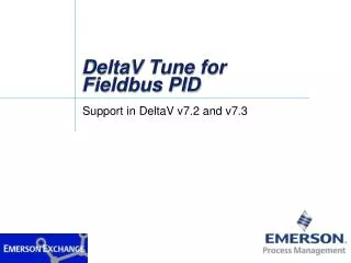
DeltaV Overview. Upon completion of this module, you will be able to identify DeltaV System architecture types Software components System capacities. Objectives. 10BaseT Cable Maximum Length 100m (330ft). Workstation. Controller. Primary Hub. Secondary Hub.

E N D
Upon completion of this module, you will be able to identify DeltaV System architecture types Software components System capacities Objectives
10BaseT Cable Maximum Length 100m (330ft) Workstation Controller Primary Hub Secondary Hub 10BaseT CableMaximum Length 100m (330ft) DeltaV System Architecture
The figure above illustrates a basic DeltaV Control Network. Refer to DeltaV Books Online for additional information about the DeltaV system architecture. DeltaV System Architecture
Multiple Nodes W o r k s t a t i o n P r i m a r y H u b S e c o n d a r y H u b S y s t e m P o w e r S u p p l y , C o n t r o l l e r , a n d I / O S u b s y s t e m L e g e n d : P r i m a r y C o n t r o l N e t w o r k S e c o n d a r y C o n t r o l N e t w o r k DeltaV System Architecture
Multiple Nodes The figure above illustrates a DeltaV Control Network with eight nodes. Maximums: 120 — Nodes 100 — Controllers / Simplex or Redundant Pairs 60 — Workstations Note: A server may be required depending on system size. Refer to DeltaV Books Online for additional information about the DeltaV system architecture. DeltaV System Architecture
2-Wide Power/Controller Carrier 8-Wide I/OInterface Carrier Mounting Screw DIN Rail I/O Card I/O Terminal Block DeltaV I/O Interface
The I/O Subsystem includes I/O Interfaces mounted on one or more 8-wide I/O Interface Carriers and an optional power source that provides power to field devices. The I/O Interface consists of the following components as illustrated above: I/O Terminal Block which snaps onto the I/O Interface Carrier to provide screw termination's for field wiring. I/O Card which snaps over the I/O Terminal Block on the I/O Interface Carrier which converts field signals to a digital format for control and communications. Refer to DeltaV Books Online for additional information about the DeltaV System architecture. DeltaV I/O Interface
Analog Inputs Series 2 AI, 8 Channel, 4 to 20 mA, HART AI, 8 Channel, 4 to 20 mA, HART AI, 8 Channel, 4 to 20 mA AI, 8 Channel, 1-5v I.S. AI, 8 Channel, 4 to 20 mA, HART RTD, 8 Channel Thermocouple, 8 Channel DeltaV I/O Card Types
Discrete Inputs DI, 8 Channel, 24 VDC, Isolated Series 2 DI, 8 Channel, 24 VDC, Dry Contact DI, 8 Channel, 24 VDC, Dry Contact DI, 8 Channel, 120 VAC, Isolated DI, 8 Channel, 120 VAC, Dry Contact DI, 8 Channel, 230 VAC, Isolated DI, 8 Channel, 230 VAC, Dry Contact High Density DI, 32 Channel, 24 VDC, Dry Contact I.S. DI, 16 Channel, 12 VDC I.S. Power Multifunction, 4 Channel, DI or Pulse Input SOE (Sequence of Events), 16 Channel, Standard DI or SOE DeltaV I/O Card Types
Outputs Series 2 AO, 8 Channel, 4 to 20 mA, HART 2 AO, 8 Channel, 4 to 20 mA, HART AO, 8 Channel, 4 to 20 mA I.S. AO, 8 Channel, 4 to 20 mA DO, 8 Channel, 120/230 VAC, Isolated DO, 8 Channel, 120/230 VAC, High Side DO, 8 Channel, 24 VDC, Isolated Series 2 DO, 8 Channel, 24 VDC, High Side DO, 8 Channel, 24 VDC, High Side High Density DO, 32 Channel, 24 VDC, High Side I.S. DO, 4 Channel, 12 VDC I.S. Power DeltaV I/O Card Types
FOUNDATION fieldbus Interface (Series 1 and 2) 2 Ports, maximum of 16 Devices/Port, 1900 meters DeviceNet (Series 2) 1 Port, maximum of 61 Devices, 500 meters @ 125K baud Profibus DP 1 Port, maximum of 64 Devices, 2000 meters @ 1.5M baud Actuator Sensor Interface (AS-i) 2 Ports, maximum of 31 Devices/Port, 300 meters Serial Interface (Series 1 and 2) 2 Port Modbus Protocol, RS232/RS485 or 2 Port Programmable DeltaV Communication Interface
2-Wide Power/Controller Carrier 8-Wide I/OInterface Carrier I/O Card DIN Rail I/O Terminal Block Mounting Screw Controller Controller
The DeltaV Controller mounts in the right slot of the 2-wide Power/Controller Carrier as illustrated above. Refer to DeltaV Books Online for additional information about DeltaV. Search: Installing Your DeltaV System. Controller
Hubs and switches provide a means to connect multiple nodes. Available Hub options include: 8-port 10BaseT 12-port 10BaseT 12-port 10BaseT, Fiber Optic Interface 12-port Dual-Speed 12-port Dual-Speed, w/Fiber Optic Link 12-port Dual-Speed, w/2 Fiber Optic Links 24-port Dual-Speed 24-port Dual-Speed, w/Fiber Optic Link 24-port Dual-Speed, 2 Fiber Optic Links 6-port 10MB Fiber Optic 6-port 10MB Fiber Optic, w/Twisted Pair Copper Interface Module DeltaV Hubs & Switches
Available Switch options include: 12-port 10BaseT/100Base TX Copper 12-port 10BaseT/100Base TX Copper, with Fiber Optic Link 12-port 10BaseT/100Base TX Copper, with Dual Fiber Optic Link 24-port 10BaseT/100Base TX Copper 24-port 10BaseT/100Base TX Copper, with Fiber Optic Link 24-port 10BaseT/100Base TX Copper, with Dual Fiber Optic Link 8-port 100MB Fiber Optic 8-port 100MB Fiber Optic, with Fiber Optic Link 8-port 100MB Fiber Optic, with Dual Fiber Optic Link DeltaV Hubs & Switches
Bulk Power Supply G N Power Distribution N DC Return Ground - + Pwr Fault DC Return 1 2 3 4 5 6 7 8 Bulk Power Supply 2 8 3 4 5 7 6 2-Wide Power/Controller Carrier I/O Carrier DeltaV System Power Supply
The DeltaVSystem Power Supply consists of the following options System Power Supply (AC/DC) - Input 110VAC or 220VAC System Passthrough Power Supply (DC/DC) - Input 12VDC System Power Supply (Dual DC/DC) - Input 24VDC or 12VDC System Power Supply, Intrinsically safe (DC/DC) - Input 24VDC Bulk AC to 24 VDC Power Supply Bulk AC to 12 VDC Power Supply Bulk 24 VDC to 12 VDC Power Supply DeltaV System Power Supply
Dell Intel Pentium with CD 2 serial ports 1 parallel port 17- or 21-inch monitor Hard disk Flat panel Redundant array of independent driver User Station Hardware
System Sizing 30,000 DSTs Unlimited SCADA tags 15,000 Advanced Unit Management DSTs plus 1 max. ProfessionalPLUS Station 10 max. Professional Stations 10 max. Application Stations 59 max. Operator Stations 60 max. workstations of any kind 5 max. Remote Data Servers 100 max. simplex Controllers 100 max. redundant Controllers 120 max. Nodes excluding redundant nodes 42 max. Remote Workstations System Capacity
DST licensing is based on the number of inputs and outputs as follows: Analog Output Analog Input Discrete Output Discrete Input Generally speaking each instrument wired into a set of screw terminals will require 1 DST. When identifying the required DST licensing start with the P&ID and count the number and type of instruments. The exception to would be FOUNDATION fieldbus devices, intelligent devices like this can have multiple inputs and outputs per instrument resulting in multiple DSTs for a device. Device Signal Tag (DST) Licensing
Workstations are licensed based on the functionality required as follows: ProfessionalPLUS Station –Configuration, Operation and Configuration Database node Professional Station – Configuration and Operation Operator Station – Operation Maintenance Station – Diagnostics Base Station – Select necessary functionality Application Station – Run time database plus user selected applications. User applications might be DeltaV Batch software or other third party OPC applications for interfacing to the plant business systems. Workstation Licensing
The DeltaV User Station Software consists of Operate Configuration Studio Diagnostics User Station Software Components
The DeltaV Operate (Run) is used by the operator to view and control the process. It consists of three items: Button Toolbar Working Area Alarm Banner DeltaV Operate (Configure) is used to create and edit DeltaV graphics. Access DeltaV Operate by selecting Start DeltaV OperatorDeltaV Operate DeltaV Operate
Button Toolbar Working Area Alarm Banner DeltaV Operate (Run)
Parameters Displays I/O Hierarchy Alarms Conditionals Algorithm Module DeltaV Control Module
The DeltaV Control Module contains algorithms that define the control system’s behavior. The DeltaV Module consists of the following: Hierarchy Displays Alarms Conditionals Algorithms Module I/O Parameters DeltaV Control Module
The DeltaV User Station Configuration Studio includes the following: Explorer Control Studio Configuration Assistant (Wizard) DeltaV Configuration Studio
Access the DeltaV Explorer by selecting Start DeltaV Engineering DeltaV Explorer DeltaV Explorer
The DeltaV Explorer is used to view and edit your system’s configuration. Use the Explorer’s pull-down menus to perform various DeltaV-related functions and use the buttons at the top of the DeltaV Explorer window to access other DeltaV programs. Also, use the plus and minus symbols to expand and collapse the selected item. Pull-down menus Access buttons DeltaV Explorer
Access the DeltaV Control Studio by selecting Start DeltaV Engineering Control Studio DeltaV Control Studio
A typical DeltaV Control Studio display is shown above. DeltaV Control Studio
Access the DeltaV Configuration Assistant by selecting Start DeltaV Engineering Configuration Assistant DeltaV Configuration Assistant
The DeltaV Configuration Assistant’s initial displayis shown above. DeltaV Configuration Assistant
Access DeltaV Diagnostics by selecting Start DeltaV Operator Diagnostics DeltaV Diagnostics
A typical DeltaV Diagnostics display is shown above. DeltaV Diagnostics
Step 1. Power up the DeltaV Monitor and Workstation. The initial Windows NT window appears after approximately two minutes. Step2. Simultaneously press the CTRL / ALT / DELETE keys to begin logging in. Enter the following information — as prompted — in lower case: Username: student administrator Password: dv deltav Step 3. Click the OK button or press the ENTER key to continue.Wait for DeltaV Logon window to appear and the hour glass has changed to a selector. Step 4. Log in to DeltaV using the same User name and Password specified above. Wait for the hour glass to change to a selector. Step 5. Click the OK button or press the ENTER key to continue. Wait for the hour glass to change to a selector. Select NT Desktop from the FlexLock menu bar. Note: If NT Desktop button is selected too soon, some applications may not get started. Workshop - Commissioning the Controller
View a list of decommissioned controllers by first launching the DeltaV Explorer Start DeltaV Engineering DeltaV Explorer Decommissioned controllers are listed in the Contents window of the DeltaV Explorer accessed by selecting Physical Network Decommissioned Controllers Decommissioned Controllers
CTLR-008572, shown above, is a decommissioned controller. Decommissioned State — Controller(s) are non-active members of a Control Network. For example: A new Controller added to the Control Network. Remove and Replace an existing controller, the new controller will be in a decommissioned state. A controller has been taken out of service(decommissioned) for an extended scheduled shutdown. Decommissioned State Visual Indicators Power LED (Green) ON Error LED (Red) FLASH at one second interval Active/Standby LED (Green) OFF Yellow LEDs FLASH at random Decommissioned Controllers
Identify the controller from DeltaV Explorer by selecting (left mouse button) Decommissioned Controller CTLR-008572 (right mouse button) Properties Flash lights Identify Controller
Identify State — A specific Controller is located on the DeltaV network. Identify is a property of the Controller that can be used to located a specific controller when multiple controllers are part of a DeltaV Network. Identify can be performed onDecommissioned and Commissioned Controllers. Identify State Visual Indicators Power LED (Green) ON All other LEDs FLASH at one second interval Note: Automatically terminate the identify state by closing the Identify pop-up dialog box or selecting Stop Flashing on the controller’s Properties window. Identify Controller
Commission a controller and auto-sense the I/O cards from the DeltaV Explorer by selecting the Decommissioned Controller CTLR-008572anddrag ‘n drop it onto the Control Network or existing placeholder. A Properties window appears requesting various information. Drag ‘n Drop Commissioning a Controller & Auto-Sensing I/O Cards
Commission — The act of making a controller an active member of a DeltaV Control Network. A TCP/IP address is automatically assigned by the ProfessionalPLUS Workstation at commissioning. This can be performed from the DeltaV Explorer or Configuration Assistant application. The last step of commissioning will prompt the user with a question to Auto-Sense I/O cards. Commissioning a Controller & Auto-Sensing I/O Cards