Download
1 / 67
690 likes | 970 Vues
Model Checking and Related Techniques. Liu Yang. Outline. Model Checking Techniques Introduction to MC Symbolic Model Checking Bounded Model Checking Explicit Model Checking Tackle the State Space Explosion Partial Order Reduction Compositional Reasoning Abstraction Symmetry

E N D
Outline • Model Checking Techniques • Introduction to MC • Symbolic Model Checking • Bounded Model Checking • Explicit Model Checking • Tackle the State Space Explosion • Partial Order Reduction • Compositional Reasoning • Abstraction • Symmetry • PAT: Process Analysis Toolkit • Performance Comparison • Conclusion
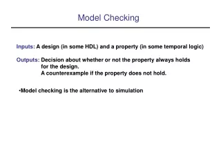
Model Checking Introduction • Model Checking is to exhaustively explore all reachable states of a finite state machine so as to tell whether a desired property is guaranteed or not. • Advantages over traditional system validation approaches based on simulation, testing and deductive reasoning • An automatic technique for verifying finite state concurrent systems • Process: modeling, specification and verification • Main challenge: state space explosion problem
Model Checking System design or code Requirements manual abstract Finite state model M Set of logical properties for each property φ automatic Model checker M |= φ ? Yes No √ ?
Model of Concurrent Systems (Unwind State Graph to obtain Infinite Tree)
Model of Concurrent Systems (Cont.) • Formally, a Kripke structure is a triple M <S,R,L>, where
Temporal logics • Temporal logics may differ according to how they handle branching in the underlying computation tree. • In a linear temporal logic (LTL), operators are provided for describing events along a single computation path. • In a Computation Tree Logics (CTL) the temporal operators quantify over the paths that are possible from a given state.
Temporal logics • Formulas are constructed from path quantifiers and temporal operators: • Path quantifier: • A: for every path • E: there exists a path • Linear Temporal Operator: • Xp: p holds next time • Fp: p holds sometime in the future () • Gp: p holds globally in the future () • pUq: p holds until q holds • In LTL, only linear temporal operators are allowed. • In CTL, each temporal operator must be immediately preceded by a path quantifier. • In CLT*, a path quantifier can prefix an assertion composed of arbitrary combinations of the usual linear-time operators.
CTL Examples • The four most widely used CTL operators are illustrated. • Each computation tree has initial state s0 as its root.
Fixpoint Algorithms • Key properties of EFp:
Model Checking Problem • Let M be the state-transition graph obtained from the concurrent system. • Let f be the specification expressed in temporal logic. M, s |= f • and check if initial states are among these.
Symbolic Model Checking • Method used by most “industrial strength” model checkers: • uses Boolean encoding for state machine and sets of states. • can handle much larger designs – hundreds of state variables. • BDDs traditionally used to represent Boolean functions.
Symbolic Model Checking with BDDs • Ken McMillan implemented a version of the CTL model checking algorithm using Binary Decision Diagrams in 1987. • Carl Pixley independently developed a similar algorithm, as did the French researchers, Coudert and Madre. • BDDs enabled handling much larger concurrent systems. (usually, an order of magnitude increase in hardware latches!)
Ordered Binary Decision Trees and Diagrams • Ordered Binary Decision Tree for the two-bit comparator, given by the formula
OBDD for Comparator Example • If we use the ordering a1 < b1 < a2 < b2 for the comparator function, we obtain the OBDD below:
Variable Ordering Problem • The size of an OBDD depends critically on the variable ordering. • If we use the ordering a1 < a2 < b1 < b2 for the comparator function, we get the OBDD below:
Symbolic Model Checking Algorithm • How to represent state-transition graphs with Ordered Binary Decision Diagrams: • Assume that system behavior is determined by n Boolean state variables v1, v2, … , vn. • The Transition relation T will be given as a boolean formula in terms of the state variables: • where v1,…, vn represents the current state and v’1,…, v’nrepresents the next state. • Now convert T to a OBDD!!
Symbolic Model Checking (cont.) • Representing transition relations symbolically: • Boolean formula for transition relation: • Now, represent as an OBDD!
Symbolic Model Checking (cont.) • How to evaluate fixpoint formulas using OBDDs: • Introduce state variables: • Now, compute the sequence • until convergence.
Problems with BDDs • BDDs are a canonical representation. Often become too large. • Selecting right variable ordering very important for obtaining small BDDs. • Often time consuming or needs manual intervention. • Sometimes, no space efficient variable ordering exists. • Next, we describe an alternative approach to symbolic model checking that uses SAT procedures.
Advantages of SAT Procedures • SAT procedures also operate on Boolean expressions but do not use canonical forms. • Do not suffer from the potential space explosion of BDDs. • Can handle functions with s to s of variables. • Very efficient implementations available.
Bounded Model Checking • Bounded model checking uses a SAT procedure instead of BDDs. • We construct Boolean formula that is satisfiableiff there is a specific finite path of length k in underlying machine. • We look for longer and longer paths by incrementing the bound k. • After some number of iterations, we may conclude no such path exists and specification holds. • For example, to verify safety properties, number of iterations is bounded by diameter of finite state machine.
Main Advantages of SAT Approach • Bounded model checking works quickly. This is due to depth first nature of SAT search procedures. • It finds finite paths of minimal length. This helps user understand the example more easily. • It uses much less space than BDD based approaches. • Does not need manually selected variable order or costly reordering. Default splitting heuristics usually sufficient.
NuSMV: A New Symbolic Model Verifier • Finite-state Systems described in a specialized language • Specifications expressible in CTL, LTL • Provides both BDD and SAT based model checking. • Allow user specified variable ordering • Uses a number of heuristics for achieving efficiency and control state explosion
Explicit Model Checking • Given a model M and an LTL formula • All traces of M must satisfy • If a trace of M does not satisfy • Counterexample • M is the set of traces of M • is the set of traces that satisfy • M • Equivalently M ¬=
Büchi Automata • Automaton which accepts infinite traces • A Büchi automaton is 4-tupleS, I,, F • S is a finite set of states • I S is a set of initial states • S S is a transition relation • F S is a set of accepting states • An infinite sequence of states is accepted iff it contains accepting states infinitely often
Example S0 S1 S2 1=S0S1S2S2S2S2… ACCEPTED 2=S0S1S2S1S2S1… ACCEPTED 3=S0S1S2S1S1S1… REJECTED
LTL and Büchi Automata • LTL formula • Represents a set of infinite traces which satisfy such formula • Büchi Automaton • Accepts a set of infinite traces • We can build an automaton which accepts all and only the infinite traces represented by an LTL formula
LTL Model Checking • Given a model M and an LTL formula • Build the Buchi automaton B¬ • Compute product of M and B¬ • Each state of M is labeled with propositions • Each state of B¬ is labeled with propositions • Match states with the same labels • The product accepts the traces of M that are also traces of B¬ (M ¬) • If the product accepts any sequence • We have found a counterexample
Nested Depth First Search • The product is a Büchi automaton • How do we find accepted sequences? • Accepted sequences must contain a cycle • In order to contain accepting states infinitely often • We are interested only in cycles that contain at least an accepting state • During depth first search start a second search when we are in an accepting states • If we can reach the same state again we have a cycle (and a counterexample)
Nested Depth First Search procedureDFS(s) visited = visited {s} for each successor s’ of s ifs’ visitedthen DFS(s’) ifs’ is accepting then DFS2(s’, s’) end if end if end for end procedure
Nested Depth First Search procedure DFS2(s, seed) visited2 = visited2 {s} for each successor s’ of s ifs’ = seed then return “Cycle Detect”; end if if s’ visited2then DFS2(s’, seed) end if end for end procedure
Explicit Model Checking • Avoid to construct the entire state space of the modeled system, can be done On-the-Fly • Some states are not generated in the product • Counterexample can be found before searching all states • Easy to optimize • Better support for asynchronous composition.
SPIN • Explicit State Model Checker • Process Algebra • Asynchronous composition of independent processes • Communication using channels and global variables • Non-deterministic choices and interleavings • Nested Depth First Search • Uses a hashing function to store each state using only 2 bits (no guarantee of soundness) • Partial Order Reduction
SPIN Example of Peterson’s Algorithm bool turn, flag[2]; byte ncrit; active proctype user0() { again: flag[0] = 1; reach: turn = 0; cs: (flag[1 - 0] == 0 || turn == 1 - 0); ncrit++; ss: assert(ncrit == 1); /* critical section */ ncrit--; flag[0] = 0; goto again } active proctype user1() { again: flag[1] = 1; reach: turn = 1; cs: (flag[1 - 1] == 0 || turn == 1 - 1); ncrit++; assert(ncrit == 1); /* critical section */ ncrit--; flag[1] = 0; goto again }
Outline • Model Checking Techniques • Introduction to MC • Symbolic Model Checking • Bounded Model Checking • Explicit Model Checking • Tackle the State Space Explosion • Partial Order Reduction • Compositional Reasoning • Abstraction • Symmetry • PAT: Process Analysis Toolkit • Performance Comparison • Conclusion
Partial Order Reduction • The interleaving model for asynchronous systems allows concurrent events to be ordered arbitrarily. • To avoid discriminating against any particular ordering, the events are interleaved in all possible ways. • The ordering between independent transitions is largely meaningless!!
The State Explosion Problem • Allowing all possible orderings is a potential cause of the state explosion problem. • To see this, consider n transitions that can be executed concurrently. • In this case, there are n different orderings and 2n different states (one for each subset of the transitions). • If the specification does not distinguish between these sequences, it is beneficial to consider only one with n + 1 states.
Partial Order Reduction • The partial order reduction is aimed at reducing the size of the state space that needs to be searched. • It exploits the commutativity of concurrently executed transitions, which result in the same state. • Thus, this reduction technique is best suited for asynchronous systems. • (In synchronous systems, concurrent transitions are executed simultaneously rather than being interleaved.)
Partial Order Reduction (Cont.) • The method consists of constructing a reduced state graph. • The full state graph, which may be too big to fit in memory, is never constructed. • The behaviors of the reduced graph are a subset of the behaviors of the full state graph. • The justification of the reduction method shows that the behaviors that are not present do not add any information.
Partial Order Reduction (Cont.) • The name partial order reduction comes from early versions of the algorithms that were based on the partial order model of program execution. • However, the method can be described better as model checking using representatives, since the verification is performed using representatives from the equivalence classes of behaviors.
Compositional Reasoning • Big systems are composed by sub-processes running in parallel. The specifications for such systems can be decomposed into properties hold in the sub processes. • Communication protocol: a sender, a network and a receiver. • Assume-Guarantee Paradigm • Verify each sub-process separately by adding assumptions on sub-process. • Combine the assumed and guaranteed properties to shown the correctness of (|| sub-processes )
Abstraction • Eliminate details irrelevant to the property • Obtain simple finite models sufficient to verify the property • E.g., Infinite state ! Finite state approximation • Disadvantage • Loss of Precision: False positives/negatives • Approaches: • Cone of influence reduction • Data abstraction
Cone of Influence Reduction • If f is an LTL formula that refers only to the variables in V, and C is the cone of influence of V, then <f, M> is satisfied if and only if <f, N> is satisfied, where N is the reduced model with respect to C.
Boolean v1, v2, v3, v4, v5, v6; Repeat forever in parallel: v1 = v2; v2 = v1 & v3; v3 = v1 & v2; v4 = v5 & v3; v5 = v4 & v6; End. (F(~ v1)): v1 will eventually become False. Boolean v1, v2, v3; Repeat forever in parallel: v1 = v2; v2 = v1 & v3; End. Cone of Influence Reduction A Simple System Model A Simple LTL property Cone of Influence Reduction
h h h h h Data Abstraction S S’ Abstraction Function h : S ! S’
Even Odd Neg Zero Pos Data Abstraction Example • Abstraction proceeds component-wise, where variables are components …, -2, 0, 2, 4, … x:int …, -3, -1, 1, 3, … …, -3, -2, -1 y:int 0 1, 2, 3, …