Download
1 / 18
370 likes | 960 Vues
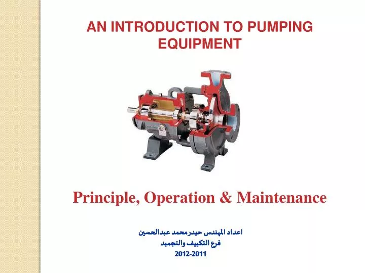
AN INTRODUCTION TO PUMPING EQUIPMENT. Principle, Operation & Maintenance. اعداد المهندس حيدر محمد عبدالحسين فرع التكييف والتجميد 2011-2012. WHAT IS THE PUMP ?. A hydrodynamic pump machine is a device for converting the energy held by mechanical energy into fluid. Pumps enable a liquid to:.

E N D
AN INTRODUCTION TO PUMPING EQUIPMENT Principle, Operation & Maintenance اعداد المهندس حيدر محمد عبدالحسين فرع التكييف والتجميد 2011-2012
WHAT IS THE PUMP? A hydrodynamic pump machine is a device for converting the energy held by mechanical energy into fluid Pumps enable a liquid to: 1. Flow from a region or low pressure to one of high pressure. 2. Flow from a low level to a higher level. 3. Flow at a faster rate. 1
There are two main categories of pump: • Rotodynamic pumps. • Positive displacement pumps. PUMP Positive displacement Rotodynamic Centrifugal Rotary Reciprocating Axial flow Mixed flow Gear Piston Turbine Lobe Diaphragm Plunger Sliding Vane 2 Screw
Centrifugal Pumps: centrifugal pumps have a rotating impeller, also known as a blade, that is immersed in the liquid. Liquid enters the pump near the axis of the impeller, and the rotating impeller sweeps the liquid out toward the ends of the impeller blades at high pressure. For low flows and high pressures, the action of the impeller is largely radial. Positive-displacement Pumps: A variety of positive-displacement pumps are also available, generally consisting of a rotating member with a number of lobes that move in a close-fitting casing. The liquid is trapped in the spaces between the lobes and then discharged into a region of higher pressure. A common device of this type is the gear pump, which consists of a pair of meshing gears. The lobes in this case are the gear teeth 3
What is the main difference between kinetic and positive displacement pumps ? The main difference between kinetic and positive displacement pumps lies in the method of fluid transfer. • A kinetic pump imparts velocity energy to the fluid, which is converted to pressure energy upon exiting the pump casing • A positive displacement pump moves a fixed volume of fluid within the pump casing by applying a force to moveable boundaries containing the fluid volume. 4
The Table below outlines some of the main differences between centrifugal pumps, reciprocating pumps and rotary pumps. Note that “centrifugal”, “reciprocating” and “rotary” pumps are all relatively broad categories 5
Volute Construction of Centrifugal Pumps 1- Casing:- Suction Impeller Casing generally are two types: I. Volute casings for a higher head. A volute is a curved funnel increasing in area to the discharge port. II. Circular casings for low head and high capacity. have stationary diffusion vanes surrounding the impeller periphery that convert velocity energy to pressure energy. 6
2-Impeller Three main categories of centrifugal pumps exist Axial flow Radialflow Mixed flow 7
H-Q Carve Once again, imagine starting a pump and raising the fluid in a vertical tube to the point of maximum elevation. On the curve this would be maximum head at zero flow. Now, rotate the running pump on its centerline 90°, until the vertical tube is now in a horizontal position. 8
Family curves At times you’ll find that the information is the same, but the presentation of the curves is different. Almost all pump companies publish what are called the ‘family of curves’. The pump family curves are probably the most useful for the maintenance engineer and mechanic, the design engineer and purchasing agent. The family curves present the entire performance picture of a pump. 9
Heads of Pump: where : Vs = Velocity of fluid in the suction pipe. Vd = Velocity of fluid in the delivery pipe. hs = Suction head. hd = Delivery head. hfs= head losses in the suction pipe. hfd= head losses in the delivery pipe. Static head (Hst) Hst = hs + hd 10
Manometric head (Hm) : but and (where ) where hf = hfs+ hfd (where HL = impeller losses) Total head (H) 11 When Vs = Vd Hence Hm = H
Typeof Impeller • There are three main categories of impeller due type of impeller’s vane, which are used in the centrifugal pumps as; • Radial vanes, Fig. (a). • Backward vanes, Fig. (b). • Forward vanes, Fig. (c). 12
a) when β2 > 90o, the Forwards curved vanes of the impeller. b) when β2 = 90o , the radial curved vanes of the impeller. c) when β2 < 90o, the Backwards curved vanes of the impeller. where : V = absolute velocity of the water. U = Tangential velocity of impeller (peripheral velocity). Vr = relative velocity of water to the wheel. Vf = velocity flow. N = Speed of impeller in (rpm). 13
Pump Efficiencies 1- Hydraulic Efficiency (ζh) The normal value varies between 60% - 90% 2- Manometric Efficiency(ζm) 3 -Volumetric Efficiency (ζv) The normal value lies between 97% to 98% 14
4- Mechanical Efficiency (ζ) It is due to losses in the shaft, coupling, and other operation losses as vibration The normal value is 95% - 98% 5 - Overall Efficiency (ζo) The normal value is 71% - 86% Discharge of a Centrifugal Pump 15
6- Power Required to Drive a Centrifugal Pump (hp) (hp) 7-1 Cavitation Cavitation is defined as the phenomenon of formation of vapor bubbles of flowing liquid in a region where the pressure of the liquid falls below its vapor pressure and the sudden collapsing of this vapor bubbles in a region of higher pressure. When the vapor bubbles collapse, a very high pressure is created. The formation and the collapse of a great number of bubbles on the surface produce intense local stresses that damage the surface by fatigue. It may occur at the entry to pumps or at the exit from hydraulic turbines in the vicinity of the moving blades 7-2 Cavitation processes in centrifugal pump The cavitation phenomenon develops in the impeller pump, when the pressure of liquid falls below the saturated vapor pressure at the prevailing temperature ( Ps< Pv of liquid), small vapor bubbles begin to form and the dissolved gases are evolved. The vapor bubbles are caught up by the following liquid and swept into a region of higher pressure, where they condense. Condensation takes place violently, accompanied by a tremendous increase in pressure, which has the character of water hammer blows. These impact follow each other in rapid succession, the vapor bubbles bursting both in the immediate vicinity of the surface attacked and in the pores causing cavitation pitting with many effecting. 16
8- The Affinity Law References: 1-Larry Bachusand Angel Custodio, (2003). Know and Understand Centrifugal Pumps. 2-Val S. Lobanoff Robert R. Ross, (1992). Centrifugal Pumps - Design and Application (2nd ed.) 3-Igor J. Karassik ,osephP. Messina,Paul Cooper and Charles C. Heald,2001. Pump Handbook(3rd ed) 17