Download
1 / 9
140 likes | 626 Vues
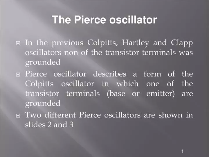
The Pierce oscillator. In the previous Colpitts, Hartley and Clapp oscillators non of the transistor terminals was grounded Pierce oscillator describes a form of the Colpitts oscillator in which one of the transistor terminals (base or emitter) are grounded

E N D
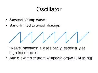
The Pierce oscillator In the previous Colpitts, Hartley and Clapp oscillators non of the transistor terminals was grounded Pierce oscillator describes a form of the Colpitts oscillator in which one of the transistor terminals (base or emitter) are grounded Two different Pierce oscillators are shown in slides 2 and 3 1
The Pierce oscillator Pierce oscillator with the emitter and base bias resistors are grounded 2
The Pierce oscillator Another form of Pierce oscillator with the emitter and base bias resistors are grounded 3
The Pierce oscillator The bias resistors which are connected across the tuned circuit has the effect of reducing the quality factor This reduces the frequency stability The Pierce oscillator grounded emitter normally has the best frequency stability The common base amplifier is most often used in high frequency oscillators because the cutoff frequency The cutoff frequency of the CB is current gain is approximately β times greater than that of the CE or CC configuration 4
The Pierce oscillator The Pierce oscillator can be analyzed using the small signal model shown below This circuit can be analyzed by using nodal analysis to find the values of VO and V By writing the nodal equations to C1 node we have 5
The Pierce oscillator The nodal equation to node that contains C2 is By solving the above two equations for VO and V we have The voltage fed back is 6
The Pierce oscillator If V is eliminated from the previous two equations we have Or In order for the circuit to oscillate, the imaginary part in the denominator must vanish and the oscillation frequency is given by 7
The Pierce oscillator In order for the phase shift to be 360º, Or For the open loop gain GH to be greater than 1 at the resonant frequency, the magnitude of VO≥1 8
The Pierce oscillator The previous VO equation can be rewritten as Or The above result is the same result that was obtained using the generalized circuit analysis 9