Download
1 / 7
70 likes | 258 Vues
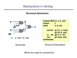
f1. a. a. nsel. f. f. f2. b. b. sel. sel. f = . a • sel’ + b • sel. Abstractions in Verilog. Structural Abstraction. module MUX (f, a, b, sel); output f; input a, b, sel; and #5 g1 (f1, a, nsel), g2 (f2, b, sel); or #5 g3 (f, f1, f2); not g4 (nsel, sel); endmodule.

E N D
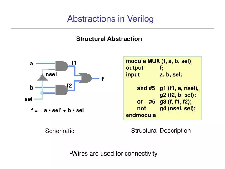
f1 a a nsel f f f2 b b sel sel f = a • sel’ + b • sel Abstractions in Verilog Structural Abstraction module MUX (f, a, b, sel); output f; input a, b, sel; and #5 g1 (f1, a, nsel), g2 (f2, b, sel); or #5 g3 (f, f1, f2); not g4 (nsel, sel); endmodule Structural Description Schematic • Wires are used for connectivity
f1 a a nsel f f f2 b b sel sel f = a • sel’ + b • sel Behavioral Abstraction module MUX (f, sel, b, c); output reg f; input sel, a, b; always @ (sel or a or b) begin if (sel == 1) f = a; else f = b; end endmodule • Sequential statements • Registers are assigned • Word-level arithmetic can be used
f1 a a nsel f f f2 b b sel sel f = a • sel’ + b • sel Dataflow Abstraction module MUX (f, sel, a, b); output reg f; input sel, a, b; wire nsel, f1, f2; assign nsel <= ~sel; assign f1 <= a && nsel; assign f2 <= b && sel; assign f <= f1 || f2; endmodule • Continuous assignment statement • Can only assign wires, not registers • Assign is evaluated whenever the righthand side changes • Not allowed inside process blocks
State Machine Abstractions • Moore machine - output is determined by state, not input • Sequential design - contains flip-flops (2)
Behavioral Description, State Machine • One block defines state transitions, one defines outputs, one updates ffs
Moore Machine Structure • Structural design - combinational logic + flip-flops • State update logic + output logic