Download
1 / 24
240 likes | 477 Vues
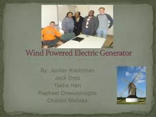
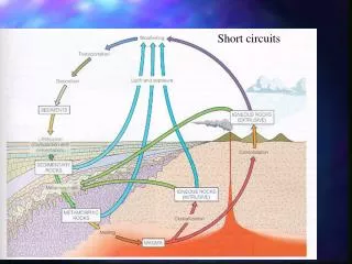
Detection of inter-coil short circuits in wind generator windings. Ante Elez Ph.D. Mate Jelavić Ph.D. Prof. Stjepan Car Ph.D. Inter-coil short circuit in wind generators. - Short circuits in generator windings lead to severe damage: long down time , high repair costs .

E N D
Detection of inter-coil short circuits in wind generator windings Ante Elez Ph.D. Mate Jelavić Ph.D. Prof. Stjepan Car Ph.D.
Inter-coil short circuit in wind generators • - Short circuits in generator windings lead to severe damage: • long down time, • high repair costs. • Generator malfunction is especially severe for direct drive machines, • Detection of generator short circuit could shut-down turbine before short circuit escalates, • Requirements upon detection methods: • on-line processing, • reliable, • unambiguous.
Inter-coil short circuit detection methods • - Two fault detection methods are presented: • inter-coil short circuit in excitation winding, • inter-coil short circuit in armature winding. • Fault detection methods are result of FEM calculations and measurements on real machine. FEM calculations 3 Evaluation of calculated magnetic field waveforms in correct and faulty condition. 1 FAULT DETECTION METHODS Calculation results 2 Confirmation of calculation results on real machine. 4
Inter-coil short circuit detection methods • List of analyzed machine conditions for witch calculations and measurements have been performed. 1 – inter coil short circuits of 10% turns of excitation winding coil, 2 – inter coil short circuits of 5% turns of excitation winding coil, 3 – inter coil short circuits of 2,5% turns of excitation winding coil, 4 – inter coil short circuits of 14% turns of armature winding coil, 5 – inter coil short circuits of 10% turns of armature winding coil, 6 – inter coil short circuits of 5% turns of armature winding coil,
Inter-coilshort circuit in excitation winding Q pole 1 pole 2 pole 3 pole 4 pole 5 pole 6 pole 57 pole 58 pole 59 pole 60 tp 2tp 4tp 3tp t Q - MAINEMF ADDITIONALEMF Q a1 Q a2 t MAINEMF TOTAL EMF Q even t Q fault Q odd Beven t TOTAL B1 Bfault Bodd MAINB1
Inter-coilshort circuit in excitation winding pole pitchp ADDITIONALEMF Q a1 Q a2 t For 60 pole machine: S = S For 2p pole machine: Q a1 p = Q a2 59 p Q a1= 59 Q a2 2p-1 2p B n= - —— (N knl) Q a1+Q a2= Q N 59 60 1 2p Q a1= — (Q N) B (n±i)= - — (N knl) 1 60 Q a2= — (Q N) 1 2p B (n±i)= + — (N knl) knl – factor determined by the slope of generator open circuit characteristic.
Inter-coilshort circuit in excitation winding Curve 1 – Flux density observed from stator tooth, Curve 2 – Voltage induced in small measuring coil placed on stator tooth, Curve 3 – Integrated voltage waveform from Curve 2.
Inter-coilshort circuit in excitation winding Flux density over pole pitch monitored from stator core tooth with inter-coil short circuits in excitation winding on pole no. 59, for tree values of excitationcurrent I0. ‘→I0=45 A, ‘‘→I0=25 A, ‘‘‘→I0=15 A. Curve 1’, 1’’, 1’’’ – for all odd poles, Curve 2’, 2’’, 2’’’ – for all even poles, Curve 3’, 3’’, 3’’’ – for polewith inter-coil short circuit.
Inter-coilshort circuit in excitation winding • Best sensitivity for excitation winding inter-coil short circuit detection can be achieved with measurement of magnetic field inside air gap. Fault detection sensitivity is decreasing with distance between the measurement point from the air gap. • Direct measurement and analysis of magnetic field waveform for unsaturated machine gives reliable detection of inter-coil short circuit in excitation winding coils. • Direct measurement and analysis of magnetic field waveform for saturated machine gives unreliable detection of inter-coil short circuit in excitation winding coils. • This is valid for magnetic field and flux density measurement in air gap,inside stator tooth and inside stator core. • Best sensitivity for excitation winding inter-coil short circuit detection forsaturated machine can be achieved with differential magnetic field measurementin air gap.
Inter-coilshort circuit in excitation winding S S S N N S, N – rotor pole N S Differential magnetic field measurement in air gap. N S N S N Ms 2p U2 wedge U1 U1 – U2 0 symmetric condition U1 – U2 0 possible inter-coil short circuits U1 – U2
Inter-coilshort circuit in excitation winding U1, U2 → voltage induced in measuring coilwires placed on stator winding wedge, U1-U2 → total measuring coil voltage.
Inter-coilshort circuit in excitation winding Voltage waveform induced in measuring coil Ms2p for wind generator. Curve 1 – voltage induced in measuring coil with inter-coil short circuits in one pole, Curve 2 – voltage induced in measuring coil without inter-coil short circuits, Curve 3 – integrated voltage waveform from curve 1, Curve 4 - integrated voltage waveform from curve 2.
Inter-coilshort circuit in excitation winding • Differential magnetic field measurement in machine air gap is innovative methodfor detecting excitation winding inter-coil short circuits. • Method is tested on small four pole generator model specially adopted forsimulation of inter coil short circuits. Calculated results have been confirmed by measurements on real machine. • If method is properly applied inter-coil short circuits in excitation winding can beunambiguously detected.
Inter-coil short circuit in armature winding Flux density waveform monitored from rotor pole shoe. Curve 1 – with 14 short circuited turns, Curve 2 – with 10 short circuited turns, Curve 3 – with 5 short circuited turns, Curve 2 – without short circuited turns.
Inter-coil short circuit in armature winding Frequency analyses of the flux density waveform monitored from a rotor pole shoe. 1 – with presence of armature inter-coil short circuits, 2 – without presence of armature inter-coil short circuits.
Inter-coil short circuit in armature winding • Inter-coil short circuit in armature winding is localized magnetic field disturbance, and it can bee detected within air gap from stator and rotor side. • If monitored from stator side distance of the stator slot comprising the short circuited turn and measuring sensor significantly affects the success of the failure detection.The pole pitch represents a limiting distance. Therefore, to ensure a successful and reliable detection of the described failure, quite a large number of sensors should be incorporated into the machine and placed at the distance one from another that will enable failuredetection. • In the contrary, when flux density within the air gap is measured from a rotor pole shoe, only one sensor will be sufficient for a successful and reliable detection of the analyzed failure. A sensor for flux density measurement should be fitted on any of the rotor pole shoes. When the sensor, which is rotating together with the rotor, faces a failure, from measuring data inter-coil short circuits in armature winding coils can be detected.
Measurement results analog data, digital data. 1 to control system 2 on stator 3 RF 1 on rotor 3 1 – Hall sensor, measuring coil 2 – processing units, 3 – wireless bridge. 2
Measurement results Measured and calculated flux density waveform in wind generator air gap. Curve 1 – measurement with Hall sensor on stator tooth, Curve 2 – calculation, Curve 3 – measurement with Hall sensor on rotor pole shoe, Curve 4 – calculation.
Measurement results Integrated voltage waveform induced in measuring coil Ms2τp Curve 1 – without inter-coil short circuits, Curve 2 – with inter-coil short circuits of 2,5% turns in excitation winding coil, Curve 3 – with inter-coil short circuits of 5% turns in excitation winding coil.
Measurement results Flux density waveform monitored from rotor pole shoe with inter-coil short circuits in armature winding. Curve 1 – measurement, Curve 2 – FEM calculation.
Conclusion • New innovative methods for detection of inter-coil short circuits in wind generator excitation and armature winding are presented. • Methods are based on FEM calculation results. • Methods are confirmed with measurements on real machine. • Fault detection methods are implemented in fault detection system which can be implemented in wind generator.