Download
1 / 33
330 likes | 450 Vues
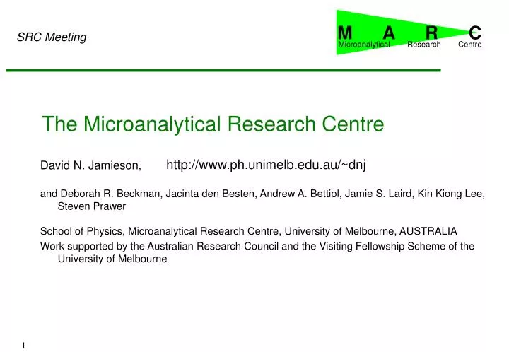
M A R C. Microanalytical Research Centre. SRC Meeting. The Microanalytical Research Centre. http://www.ph.unimelb.edu.au/~dnj. David N. Jamieson , and Deborah R. Beckman, Jacinta den Besten, Andrew A. Bettiol, Jamie S. Laird, Kin Kiong Lee, Steven Prawer

E N D
M A R C Microanalytical Research Centre SRC Meeting The Microanalytical Research Centre http://www.ph.unimelb.edu.au/~dnj David N. Jamieson, and Deborah R. Beckman, Jacinta den Besten, Andrew A. Bettiol, Jamie S. Laird, Kin Kiong Lee, Steven Prawer School of Physics, Microanalytical Research Centre, University of Melbourne, AUSTRALIA Work supported by the Australian Research Council and the Visiting Fellowship Scheme of the University of Melbourne 1
Facilities of the Centre • NEC 5U Pelletron accelerator with RIEF funded upgrade to make it one of the brightest accelerators in the world for nuclear microprobe operation ($2,000,000+) • Two MeV ion microprobe beam lines and associated instrumentation ($1,000,000 each) • Dilor confocal Raman spectrometer ($500,000) • Joel UHV AFM ($700,000) • Distributed computer network of one DEC Alpha workstation and more than 20 satellite workstations and PC's ($100,000). • Pulsed Laser Deposition System ($1,000,000) • This combination of instruments is unique worldwide for one research Centre! 2
1nm 20 nm ATOMIC RESOLUTION USING THE UHV ATOMIC FORCE MICROSCOPE Atomic Force Microscope Image of Si 7 x 7 surface reconstruction. Each dot is a single Si atom. Lithography: Al Cimmino leaves his mark on a piece of Silicon. The width of the line is 2 nm and its depth is 0.2nm. 3
Academic Staff Val Gurarie David Jamieson Michelle Livett Steven Prawer Postdoctoral Fellows Jeff McCallum Paul Spizzirri +3 Infrastructure Alberto Cimmino Roland Szymanski William Belcher Eliecer Para Students Paul Otsuka Matthew Norman Elizabeth Trajkov Brett Johnson Amelia Liu Leigh Morpheth David Hoxley Andrew Bettiol Deborah Beckman Jacinta Den Besten Kristie Kerr Louie Kostidis Poo Fun Lai MARC People • Jamie Laird • Kin Kiong Lee • Geoff Leech (part time RMIT) • Debora Lou-Greig • Ming Sheng Liu • Glenn Moloney • Julius Orwa • Arthur Sakalleiou • Russell Walker 4
Photons and MeV ions interact with matter electrons ions x-rays photons ions nuclear fragments ions electrons holes 5
30 keV e 60 keV e 2 MeV He 5 m 10 m 0.5 m • Deep probe • Large damage at end of range keV electrons and MeV ions interact with matter • Restricted to 10 m depth, large straggling • Low beam damage 6
Distance of probe ion from the nucleus Increasing energy of induced radiation Analysis modes CLOSE MeV • NRA: Nuclear reactions probe inner nucleus • RBS: Rutherford Backscattering Spectrometry probes nucleus • PIXE: Particle induced x-ray emission probes inner electron shells • IBIC: Ion beam induced charge probes band gap • IL: Ionoluminescence probes band gap eV FAR 7
The Melbourne Pelletron Accelerator • Installed in 1975 for nuclear physics experiments. • National Electrostatics Corp. 5U Pelletron. • Now full time for nuclear microprobe operation. • Will be state-of-the-art following RIEFP upgrade Inside Outside 8
x-ray detector 1 m From accelerator Scanner Beam steerer & Object collimators Aperture collimators Microscope Probe forming lens SSBs Sample stage goniometer Low vibration mounting Ion pumps Nuclear microprobe essential components 9
Re-entrant microscope port & light SSB detectors SiLi port Specimen Chamber inside • 30 mm2 Si(Li) x-ray detector • 25 and 100 msr PIPS particle detectors at 150o • 75 msr annular detector 10
MARC activities 1995 - 1999 IBMM: Ion Beam Modification of Material, IBA: Ion Beam Analysis 11
2: Decay from L or M shell produces K x-rays PIXE: Transitions following ionization 1: Knock out electron from K-shell (ionization) • G. Moseley discovered this in 1910 • From elementary quantum mechanics, the K x-ray energy is given by: EKa = (ke2/2a0). (3/4)(Z-1)2 (Hydrogenic n=2 to n=1 transition) a0 = Bohr radius, k = Coulomb constant, e = electron charge 12
The work of Jacinta den Besten PIXE: Au loaded Mineral - Pyrite (FeS2) • Specimen from Emperor Au mine in Fiji • Called Fool’s gold in Australia • Also find much gold in this mineral in Australia • How did the Au get into the mineral? 13
PIXE: Mapping Pyrite crystal from windows in energy spectrum • Crystals grow from melt by heteroepitaxy under geological conditions • Elemental zoning can be mapped with 3 MeV proton induced x-ray emission • Au appears incorporated into crystals as: • Au metal lumps • Lattice substituted uniform distribution 500x500 m2 scan size 14
The work of Arthur Sakellariou 4.5 MeV 3-D tomography of 40 mm catalyst particle X-ray Detector Rotation Particle Detector 2-D scan Sample 15
Heavy nucleus Little recoil High energy RBS: Rutherford Backscattering Spectrometry Light nucleus Lots of recoil Low energy Useful for measuring light elements 16
NRA: Nuclear Reaction Analysis Light nucleus BEFORE Useful for measuring lightest elements Transmutednucleus AFTER Very high energy 17
Au Pd Pd 2 MeV He+ MCT Metal(Au) Detector GaAs Au HgCdTe GaAs Pd 100 m HgCdTe Non-destructive RBS tomographic image RBS: 2 MeV He+ depth profiling of IR photodetectors Photo 18
The work of Deborah Beckman (a) (b) 50mm 50mm Example: CCM analysis of epitaxial GaN films • GaN is a novel wide band-gap semiconductor with many desirable properties • Single crystal films are required for microelectronic device applications • Epitaxial growth of GaN on sapphire is possible, but displays growth defects • CCM image shows excellent crystallinitychi-min<3%, t=0.53mm 2.5 MeV He+, 200 mm scan 19
The work of Frank Watt Micromachining in PMMA at the National University of Singapore • 2.3 MeV protons on PMMA • This work dates from 1996, much more interesting structures are now available • See review by Prof F. Watt, ICNMTA6 - Cape Town, October 1998 20
MeV ions interact with matter • MeV ions penetrate deeply without scattering except at end of range. • Energy loss is first by electronic stopping • Then nuclear interactions at end of range 3 MeV H+ PMMA substrate(side view) surface 100 m 21
Micomachining • Example • Proton beam lithography • PolyMethyl MethAcrylate (PMMA) • exposure followed by development • 2 MeV protons • clearly shows lateral straggling Protons 10 m Sideview 22
Single ion tracks (Huang and Sasaki, “Influence of ion velocity on damage efficiency in the single ion target irradiation system” Au-Bi2Sr2CaCu2Ox Phys Rev B 59, p3862) • Latent damage from single-ion irradiation of a crystal(230 MeV Au into Bi2Sr2CaCuOx) • Lighter ions produce narrower tracks! Depth 1 mm 3 mm 5 mm 7.5 mm 23
Contact formation Credits:A: www.ifm.liu.se/Applphys/ftir/sams.htmlB-D: IBM Research Labs www.zurich.ibm.com/~bmi/sams.html Self Assembled Monolayers for nanofabrication C Monolayer deposition A AFM images of end-groups D B 24
Single MeV heavy ions are used to produce latent damage in plastic Etching in NaOH develops this damage to produce pores Light ions produce smaller pores MeV ion etch pits in track detector Heavy ion etch pit 3. Etch 2. Latent damage 1. Irradiate Scale bars: 1 mm intervals From: B.E. Fischer, Nucl. Instr. Meth. B54 (1991) 401. 25
Read-out state of “qubits” Etch latent damage& metallise MeV 31P implant Resist layer Si substrate 26
The work of Mark von Bibra Device fabrication:Layered waveguides • Ion energy ---- waveguide depth 27
The work of Mark von Bibra 20m Optical Materials • Fused Silica • Increase in density at end of range • Increase in refractive index (up to 2%) at end of range 2 MeV H+ silica surface laser light emerging 28
The work of Mark von Bibra Device fabrication: Other passive devices • Waveguide couplers 29
The work of Mark von Bibra Device fabrication: Y junctions • Waveguide splitters • Composite image (with enhancement) • Waveguide Couplers 30
References • Materials Analysis using a Nuclear Microprobe • Breese, Jamieson and King • John Wiley & Sons, New York 1996 31
M A R C O Microanalytical Research Centre Commercial Organisation Made in Melbourne Other microprobes (1999) Nuclear Microprobe Laboratories 32
Conclusions • Structural characterisation: • Spatial resolution of for conventional IBA 0.4 m • Elemental sensitivity with PIXE 10 ppm • Depth resolution with RBS 50 nm • Lattice location studies with ion channeling • Electrical characterisation • Spatial resolution for IBIC 0.1 m • Mapping of charge trapping an recombination centres • Sub-trace optically active colour centres with luminescence • 3D density and elemental mapping with tomography • Stay tuned for further developments...... 33