Download
1 / 24
240 likes | 420 Vues
EET 1131 Unit 3 Basic Logic Gates. Read Kleitz , Chapter 3. Homework #3 and Lab #3 due next week. Quiz next week. The NOT operation (complement) is shown with an overbar. Thus, the Boolean expression for an inverter is X = A . A. X. The Inverter.

E N D
EET 1131 Unit 3Basic Logic Gates • Read Kleitz, Chapter 3. • Homework #3 and Lab #3 due next week. • Quiz next week.
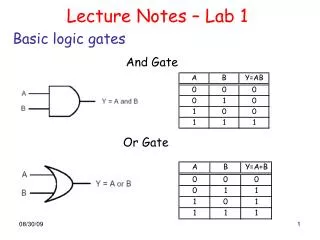
The NOT operation (complement) is shown with an overbar. Thus, the Boolean expression for an inverter is X =A. A X The Inverter The inverter performs the Boolean NOT operation. When the input is LOW (0), the output is HIGH (1); when the input is HIGH, the output is LOW. 0 1 1 0
A X The Inverter Example waveforms: A X
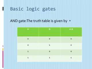
A A X X The AND Gate B B The AND gate produces a HIGH output when all inputs are HIGH; otherwise, the output is LOW. For a 2-input gate, the truth table is 0 0 0 1 1 0 1 1 0 0 0 1 The AND operation is usually shown with a dot between the variables but it may be implied (no dot). Thus, the AND operation is written as X = A .B or X = AB.
A A X X The AND Gate B B Example waveforms: A B X
The AND Gate Example A Multisim circuit is shown. XWG1 is a word generator set in the count down mode. XLA1 is a logic analyzer with the output of the AND gate connected to first (upper) line of the analyzer. What signal do you expect to on this line? Solution The output (line 1) will be HIGH only when all of the inputs are HIGH.
A X A X The OR Gate B B The OR gate produces a HIGH output if any input is HIGH; if all inputs are LOW, the output is LOW. For a 2-input gate, the truth table is 0 0 0 1 1 0 1 1 0 1 1 1 The OR operation is shown with a plus sign (+) between the variables. Thus, the OR operation is written as X = A + B.
A X A X The OR Gate B B Example waveforms: A B X
The OR Gate A Multisim circuit is shown. XWG1 is a word generator set to count down. XLA1 is a logic analyzer with the output Example connected to first (top) line of the analyzer. The three 2-input OR gates act as a single 4-input gate. What signal do you expect on the output line? The output (line 1) will be HIGH if any input is HIGH; otherwise it will be LOW. Solution
The NAND operation is shown with a dot between the variables and an overbar covering them. Thus, the NAND operation is written as X = A .B (Alternatively, X = AB.) A A X X The NAND Gate B B The NAND gate produces a LOW output when all inputs are HIGH; otherwise, the output is HIGH. For a 2-input gate, the truth table is 0 0 0 1 1 0 1 1 1 1 1 0
A A X X The NAND Gate B B Example waveforms: A B X The NAND gate is particularly useful because it is a “universal” gate – all other basic gates can be constructed from NAND gates.
The NAND Gate Example A Multisim circuit is shown. XWG1 is a word generator set in the count up mode. A four-channel oscilloscope monitors the inputs and output. What output signal do you expect to see? Solution The output (channel D) will be LOW only when all of the inputs are HIGH. Inputs
The NOR operation is shown with a plus sign (+) between the variables and an overbar covering them. Thus, the NOR operation is written as X = A + B. A X A X The NOR Gate B B The NOR gate produces a LOW output if any input is HIGH; if all inputs are LOW, the output is HIGH. For a 2-input gate, the truth table is 0 0 0 1 1 0 1 1 1 0 0 0
A X A X The NOR Gate B B Example waveforms: A B X The NOR operation will produce a LOW if any input is HIGH.
Integrated Circuits Cutaway view of DIP (Dual-In-line Package) chip: The TTL series, available as DIPs are popular for laboratory experiments with logic.
Integrated Circuits DIP chips and surface mount chips Pin 1 Dual in-line package Small outline IC (SOIC)
Integrated Circuits • Chip Densities: • Small scale integration (SSI): <=10 gates per chip. • Medium-scale integration (MSI): 10 to 100 gates per chip. • Large-scale integration (LSI): 100 to 10,000 gates per chip. • Very large-scale integration (VLSI): 10,000 to 100,000 gates per chip.
Programmable Logic Programmable logic devices (PLDs) are an alternative to fixed function devices. The logic can be programmed for a specific purpose. In general, they cost less and use less board space than fixed function devices.
Figure 3.50 Pin configuration diagrams for some common gate configurations.
Website for Datasheets • Many websites have datasheets for logic chips. • The best site is Texas Instruments: www.ti.com • Type the chip number (such as 7404) in the Search box. • For some chips, the original part number is obsolete and no longer available. In such cases, inserting LS often works. Example: 74LS10.
Troubleshooting • Troubleshooting means finding and fixing faults in a circuit or system that’s not working correctly. • Your first step in troubleshooting a digital circuit on the breadboard should always be to verify that the voltage at each chip’s power and ground pins are actually +5 V and 0V. • After that, use your knowledge of truth tables to find the gates that are not producing the correct outputs.
Multisim Troubleshooting • Multisim lets you insert the following kinds of faults into digital components: • An open pin • Two pins shorted together • A pin shorted to VCC (constant HIGH) • A pin shorted to ground (constant LOW) • Your book has Multisim troubleshooting problems that I’ll assign on some homeworks. You can download the files for these from the book’s website. • To troubleshoot them, attach switches to input pins and probes to output pins.