Download
1 / 26
270 likes | 438 Vues
Analog and Digital Transmission Interfaces and Multiplexing (Physical Layer). Lita Lidyawati 2012. Multiplexing. Multiplexing (“ muxing ”) allows multiple flows to share a channel , within the limits of the overall capacity. Multiplexing (‘cont).

E N D
Analog and Digital Transmission Interfaces and Multiplexing (Physical Layer) Lita Lidyawati 2012
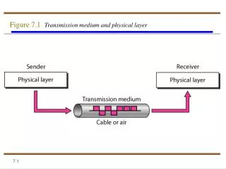
Multiplexing • Multiplexing (“ muxing”) allows multiple flows to share achannel, within the limits of the overall capacity.
Multiplexing (‘cont) • Frequency division (FDM) - analogous to radio spectrumwithin a cable; not a good environment for data due to noise from “baseband loading”. • Time division (TDM) - interleaves bits from slower datastreams onto a single, faster data stream.
Modulation • Modulation means varying some property of a signalto impress information on the signal
Amplitude Modulation • Assuming amplitude 1 = binary 0, and amplitude 2 = binary 1,this signal would represent 0011010
Phase Modulation + =
Quadrature Amplitude Modulation • first and second bit taken as a binary number are the multiple o f 90o • third bit indicates the amplitude
Quadrature Amplitude ModulationExample • Let's encode a big bit stream: 001010100011101000011110 • We break it up into 3-bit triads:001-010-100-011-101-000-011-110
Digital Transmission • The foregoing discussion assumes the signal is modulatedaccording to some continuous input that behaves in a wayanalogous to the information, for example, the output current from a microphone. • Such a sample can be represented as binary numbers, or a “digital” signal
Encoding a Digital Signal • An encoder samples, or measures the amplitude of the incominganalog signal 8,000 times a second • The amplitude of each sample is given a pre-established 8-digitbinary code, which is determined by the height of the sample. • Each 8-digit binary code is transmitted behind the 8-digit binarycode of the previously encoded sample in the conversation,creating a signal of 64,000 b/s (8,000 samples a second at 8 bitsper sample.
Multiple Bits per Baud • QAM is an example of the way modern modems can pack a lotof information into a sample. • Depending on the quality of the analog channel, it is possibleto encode several bits into every sample taken form thechannel: multiple bits per baud • Given n levels of signal that can be discriminated in eachsample based on amplitude frequency or phase, the bit rate is:
Multiple Bits per Baud • where C is the channel capacity as before and b is thesignallingrate (also called sampling rate or baud rate) • Shannon’s law defines the absolute limit for C
Multiple Bits per Baud • Sample analog voice signal at the Nyquist rate = 2 fH (twicethe highest frequency if fL= 0), or2 X 4000 Hz = 8000 samples per second • Convert each sample to an 8-bit binary number (called quantizing) using Pulse Code Modulation (PCM) • Send this digital data as 8 (bit samples) X 8000 (samples per second), or 64,000 bps
Digital Transmission of Voice • A group of 24 voice channels requires • 24 X 64 kbps = 1,536,000 bps • which can fit on a T1 carrier channel
Digital Audio Fidelity • 8-bit PCM is very adequate for telephone use but is not “highfidelity” with regard to either noise or bandwidth. • When a digitally encoded signal is converted back to analog,there is an added “noise of quantization”: • thus for 8-bit coding S/N=216=65,536=48.2dB so the noise willbe no better than 48.2 dB below maximum possible signal level
Digital Audio Fidelity • For CDROM quality fH = 20kHz and fL= 0; and the sample isencoded in 16 bits; thus
Digital Pulse Codes • Purpose: Make efficient use of available bandwidth while avoiding errors (also may be designed to eliminate DC component, as required by some media) • Non-Return to Zero-L (NRZ-L): straight binary data • Manchester: 01 = 1; 10 = 0 (two baud per bit); guaranteesan equal number of ones and zeros; requires 2x bandwidth in medium • Bipolar alternate mark inversion (AMI): a pulse for each one; every pulse changes polarity
Physical Interfaces • EIA-232-D (“ RS-232”) • Most common serial interface • If used for asynchronous transmission, the interface can work with as few as five wires. • Many more pins are defined
Physical Interfaces • EIA-449 (“ RS-449”) • Higher data rate (up to 2 Mbps) • Balanced line capable • Common on 56/64 kbps and T1/E1 links • Variations include RS-422, V.35 • Built-in loopback capability