Download
1 / 13
460 likes | 2.92k Vues
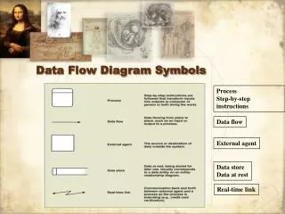
Yourdon and Coad Process Notations. Yourdon and Coad Datastore Notation. Gane and Sarson Process Notation. Gane and Sarson Datastore Notations. Data Flow Diagram Notations .

E N D
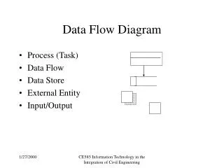
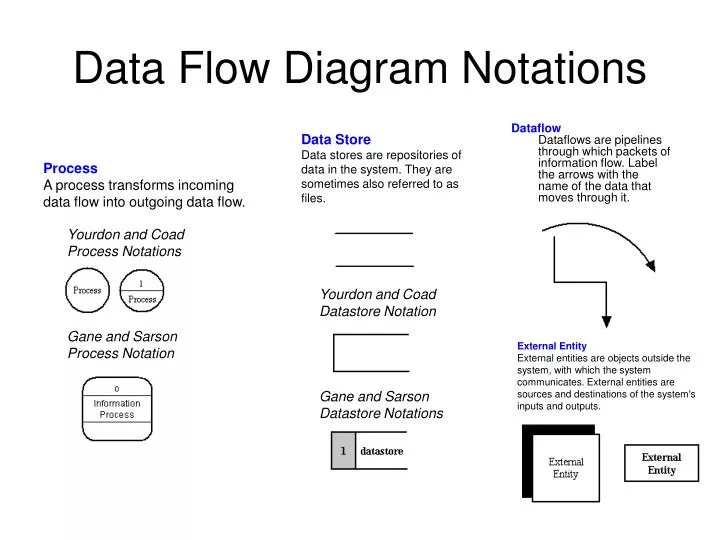
Yourdon and CoadProcess Notations Yourdon and CoadDatastore Notation Gane and SarsonProcess Notation Gane and SarsonDatastore Notations Data Flow Diagram Notations DataflowDataflows are pipelines through which packets of information flow. Label the arrows with the name of the data that moves through it. Data StoreData stores are repositories of data in the system. They are sometimes also referred to as files. ProcessA process transforms incoming data flow into outgoing data flow. External EntityExternal entities are objects outside the system, with which the system communicates. External entities are sources and destinations of the system's inputs and outputs.
Data Flow Diagram LayersDraw • Data flow diagrams are drawn in several nested layers • A single process node on a high level diagram can be expanded to show a more detailed data flow diagram. • Draw the context diagram first, followed by various layers of data flow diagrams.
Context Diagrams • A context diagram is a top level (also known as Level 0) data flow diagram. It only contains one process node (process 0) that generalizes the function of the entire system in relationship to external entities.
DFD levels The first level DFD shows the main processes within the system. Each of these processes can be broken into further processes until you reach pseudocode.
Level 0 – DFD ATM User request Transaction requests member banks ATM display Balance Information receipt Printer Account data Information request account database
A level 1 DFD Printer/display Customer’s Card details Rejection message 1. Validate Customer access 2. Reject transaction \and end session Access map PIN Access authorization Network directory customer Rejection message 3. Obtain Details of transaction Access permissions 4. Validate transaction select options Transaction request
Network directory A level 2 DFD Customer’s Card details Cannot Read card 1.1 Read Details From card Printer/display Card data Encoded pin 1.2 Check Expiry date And bank group customer 1.3 Request Pin And match Max 3 attempts PIN Card Validation data Access map Invalid pin Access authorization
Validate deposit Display account Make inquiry account # & deposit account data balance query deposit transaction account database Another Approach to the ATM Level 1 Get deposit Get inquiry member banks User bank name error error account # account # & deposit account display Validate inquiry account # Printer Do deposit transaction Create account summary account data