Download
1 / 58
600 likes | 801 Vues
Modems. Based on material from Chapter 6 in Computer Networks and Internets (Comer, Third Edition). Local versus Non-Local Communication. RS-232 is a local means of communication.

E N D
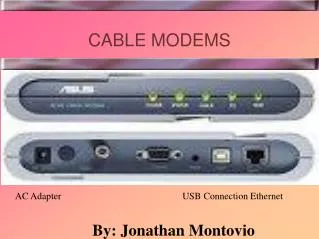
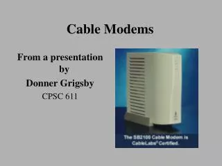
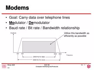
Modems Based on material from Chapter 6 in Computer Networks and Internets (Comer, Third Edition)
Local versus Non-Local Communication • RS-232 is a local means of communication. • It can be used for a computer to communicate with a modem (modulator-demodulator) but the modem prepares the signal to be sent over greater distances.
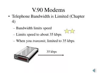
Modem • A modem converts a digital signal to an analog (actually pseudo-analog) signal more suited for transmission over long distances or receives the analog signal and converts it to the corresponding digital signal. • That is, it modulates and demodulates. • The carrier wave is an alternating current with a frequency in the AF (audio frequency range).
Attenuation • Attenuation is the lowering of signal’s amplitude (size and strength) that occurs while the signal is transmitted. • The opposite of attenuation is amplification. • Too much attenuation leads to a loss of information. • Repeaters detect the signal before it becomes too weak and amplify it. • Different frequencies different amount of attenuation.
Waveform • The waveform is the shape of the wave (voltage, current, electric field, etc.) as a function of time. • Some standard waveforms are • sinusoidal • square • sawtooth • ramped • triangular
RS-232 • The signal coming into an RS-232 port is an irregular (non-periodic) square wave
Fourier Demo • Fourier analysis states that waves that do not have a sinusoidal waveform can be thought of as being comprised of a set of sinusoidal waves of different frequencies added together. • So a square wave is a lot of sine waves added together. • Demo
They all lose their shapes in the end • The key phrase on the last page is “a lot,” it takes a lot a sine waves (especially those with high frequencies) to reproduce the sharp features in a square wave. • Two problems • Dispersion: the speed of the sine waves can depend on frequency. • The attenuation of the sine waves can depend on frequency. • The result: square waves don’t remain square.
A simple sine wave • A simple sine wave is more robust to attenuation, that is, it travels farther without significant damping (and it is unaffected by dispersion since it is only one frequency). • The problem is that a simple sine wave carries little to no information.
Carrier wave • The idea is to take advantage of a sine wave’s robustness and use it as the starting point for carrying information. • Changing (modulating) the wave inserts the information into the signal. • If one does not deviate too much from the simple sine wave, the signal should travel long distances.
Modulation • Modulation is the layering of information on a carrier. • Example: in a smoke signal, the carrier is a steady stream of smoke, and the modulation is provided by the blanket waving which puts variations into the stream of smoke. • The telecommunication industry uses either alternating currents (wired) or electromagnetic waves (wireless) as the carrier.
Modulation Types • Amplitude modulation (AM): the wave’s amplitude (size) is varied over time. • Frequency modulation (FM): the wave’s frequency (number of cycles per second) is varied over time. • Phase modulation (PM), the wave’s phase (the part of the cycle it’s in) is varied with time.
PSK • Phase-shift keying (PSK) is the fancy name for phase modulation. • Biphase: A simple version of PSK using only two phases: 0° and 180°. The state of each bit is determined according to the preceding one. The bit is 0 if the phase does not change and 1 if it changes by 180°.
Phase shifts Phase shifted Phase not shifted
QAM • Quadrature Amplitude Modulation: Uses a combination of four phases and two amplitudes to encode three bits per cycle. • With phases it’s not strictly the shape of the wave that matters but the shape of one segment compared to the previous segment.
PCM • The previous modulation schemes prepared digital signals to be sent over an traditionally analog medium (the phone system). • PCM (pulse code modulation), on the other hand, is a digital scheme for transmitting analog data. • The analog signal is sampled and digitized (a process sometimes known as quantization). • The receiver demodulates the wave recovering an analog form.
Broadband and Baseband • Broadband: Data transmission in which a medium (wire) conveys several signals at once. • Example: Cable TV • Baseband: Data transmission in which a medium conveys one signal • Example: Most communications between computers, LANS, modems, etc.
Sideband • If one analyzes the set of frequencies that go into making a modulated wave, a sideband is the part that is either above or below the carrier frequency. • The higher frequencies are known as the upper sideband; the lower frequencies are called the lower sideband. • In normal AM (amplitude modulation) transmission, both sidebands are used. But in some transmissions, one or part of a sideband may be removed.
Multiplexing • “Capable of transmitting two or more signals or messages ‘simultaneously’ on the same circuit or channel.” • Many to one • In this case, many signals to one channel.
Multiplexing (Fig. 6.6) Many signals (from different sources) being put on one shared channel.
Multiplexing (Cont.) • Dividing the bandwidth of a carrier so that multiple signals can be sent on the same carrier. • The carrier is called a channel and each signal is called a subchannel. • A multiplexer is a device that puts the various signals on the carrier.
Basic schemes of Multiplexing • Frequency Division Multiplexing (FDM): uses different frequencies simultaneously. • Time Division Multiplexing (TDM): breaks transmission into various time segments and the different signals are assigned to a segment in a round-robin fashion. • Statistical Time Division Multiplexing (STDM): time segments are assigned based on need. • Wavelength Division Multiplexing (WDM): pretty much the same as FDM but used when referring to signals sent on optical fiber.
FDM • Frequency Division Multiplexing: sending a number of signals using different frequency ranges. • Usually refers to sending signals over a wire. • If you applied the term to wireless communication, radio and television would be an example of FDM. The signals for different radio stations are sent through the same medium (“the airways”) at the same time.
TDM • Time Division Multiplexing: different signals take turns (are assigned time slots). • TDM repeatedly transmits a fixed sequence of time slots over a single transmission channel. • T-1 and T-3 lines use a combination of TDM (time division multiplexing) and PCM (Pulse Code Modulation).
T-1 • A dedicated phone connection supporting data rates of 1.544Mbits per second. • Divided into 24 channels, each supporting 64Kbits per second. • The channels can be configured to carry voice (analog) or data (digital) traffic. • Most telephone companies allow one to purchase some of these 24 channels; this is called fractional T-1 access.
T-1 (Cont.) • Used by businesses for connecting to the Internet and by Internet Service Providers (ISPs) for connecting to the Internet backbone. The Internet backbone itself consists of faster T-3 connections. • T-1’s are sometimes called DS1 lines. • More later in the semester.
T-3 Carrier • A dedicated phone connection capable of transmitting data at 43 Mbps. • Comprised of 672 individual channels (64 Kbps each). • Used by Internet Service Providers (ISPs) for connecting to the backbone and for the backbone itself. • T-3’s are sometimes called DS3 lines.
WDM and DWDM • Wavelength Division Multiplexing, and Dense Wavelength Division Multiplexing: same as FDM but applied to light as the carrier instead of electricity
Spread Spectrum • Term for varying the baseband or carrier frequency. • This scheme is used in wireless communication (e.g. cell phones) for two reasons: • To make sure the signal gets through • To make sure the signal is not intercepted
Spread spectrum (Cont.) • First, a constant-frequency may experience catastrophic interference. • This occurs when another signal is transmitted on, or very near, the frequency of the desired signal. • Catastrophic interference can be accidental (as in amateur-radio communications) or it can be deliberate (as in wartime).
Spread spectrum (Cont.) • Second, a constant-frequency signal is easy to intercept, and is therefore not well suited to applications in which information must be kept confidential between the source (transmitting party) and destination (receiving party).
Hedy Bio • Nee Hedwig Eva Maria Keisler • Was in one of the first nude scenes in cinema history – in the Czech film Ecstasy. • First husband was Fritz Mandl, arms producer/dealer in 1930’s Europe. • Escaped from Mandl and headed to Hollywood where she took the name Hedy Lamarr. • Along with pianist George Antheil, developed (and patented) “frequency hopping” technique for guiding torpedoes in a way that could not be jammed. • The implementation (they suggested player piano rolls) was too difficult at the time. The overall idea was used however in early 1960’s in US’s blockade of Cuba.
Packet • Recall that a message is broken into pieces called packets so that it can be sent over a network. A network which communicates in this way is known as is a packet-switching network. • The data is “framed” by additional information including the packet’s destination (an address).
Packet Switching • The protocol (rules for communication) for packet switching determines the additional information and its format to be included in the framing. • It might also place bounds on the size of the packets. • Packet are then sent over the network. They do not have to follow the same route. (However, many will since routers cache recently used addresses.) • After arriving at the destination, the packets must be re-assembled. The framing information must facilitate this.
Packet Switching • Popular protocols adhering to the packet switching model include: TCP/IP, X.25, and Frame Relay. • Packet switching allows a resource (e.g. the transmission lines) to be shared without any one transmission hogging or glutting a resource.
Multiplexing (Fig. 6.6) • Sharing a transmission line requires multiplexing, in this case TDM (time division multiplexing)
Getting through • Suppose a short message was sent just after a much larger message was started. • The packets of a short message are interspersed between the many more packets of a larger message allowing it to get through without waiting for the entire large message to transmit.
Circuit switching • Recall an alternative technology is circuit-switching as used for phone conversations. In this case a particular route is dedicated to the transmission between two parties. • Packet switching is better for inter-computer communication since information tends to leave the computer in bursts with “dead” times in between which would waste a dedicated resource.
ATM • Asynchronous Transfer Mode tries to provide the best of both worlds: the quality of service (guaranteed transmission rate) of circuit-switching and the efficiency of packet-switching. • ATM requires a much smaller, fixed packet size than standard packet-switching protocols. It also creates a fixed route between source and destination. • Because there is a specific route, ATM service can be tracked and billed more like one’s phone service.
ATM: Service Type • Constant Bit Rate (CBR): a fixed rate, data is sent steadily. This is analogous to a leased line. • Variable Bit Rate (VBR): a specified throughput capacity, but data sent somewhat unevenly. This is a popular choice for videoconferencing. • Unspecified Bit Rate (UBR) no guaranteed throughput levels. This is used for applications, such as file transfer, that can tolerate delays. • Available Bit Rate (ABR) guaranteed minimum capacity but allows data to be bursted at higher capacities when the network is free.
Frame • A frame is information that is sent between “nodes” as a unit. • It is typically sent serially, bit-by-bit. • It usually contains a header field and sometimes a trailer field with addressing and protocol information that "frame" the data. • Some control frames contain no data (other than protocol information, such as addresses) • E.g. Ping, ATM set up
Frame Example (Cont.) • On the previous slide, the flag and address fields make up the frame’s header. • The check sequence and second flag fields make up the frame’s trailer. • The information in sandwiched in between. • The data may itself be another frame for another (typically higher-level) protocol. Frame-relay frames often carry data previously framed by another protocol.