Download
1 / 28
280 likes | 355 Vues
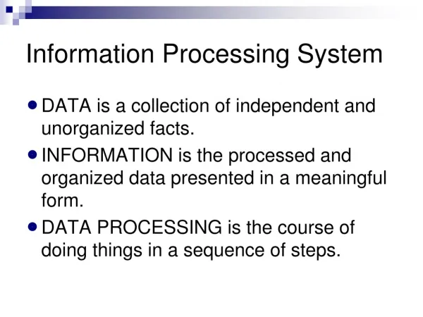
Spatiotemporal Information Processing No.2 3 components of Virtual Reality-1 Sensing System. Kazuhiko HAMAMOTO Dept. of Information Media Technology, School of Information and Telecommunication Eng., Tokai University, Japan. Today’s Contents. Virtual Reality and its 3 components (review)

E N D
Spatiotemporal Information ProcessingNo.23 components of Virtual Reality-1Sensing System Kazuhiko HAMAMOTO Dept. of Information Media Technology, School of Information and Telecommunication Eng., Tokai University, Japan
Today’s Contents • Virtual Reality and its 3 components (review) • Sensing System • Tracker • Electromagnetic induction method • Ultrasound method • Optical method • Data Glove
Virtual Reality (review) • A computer will be able to process spatiotemporal information in next generation • To access the information, the computer will use human sense • Ordinary behavior of person is also used as interface to computer. The human interface is “Virtual Reality”
Definition of “Virtual Reality” (review) • What is not actual, but has the same essence as actual thing • The world where we can access by the five senses and human behavior can be used as human interface directly • First proponent of “Virtual Reality” isJ.Lanier, USA, in 1987
3 elements of Virtual Reality (review) • 3D Environment • 3D virtual space is “natural” for human senses. • Real-Time Interaction • Real time response of computer to action of person • Autonomy • Virtual space exists even if people (user) doesn’t exist, • Virtual space exists not only as human interface but independent of user.
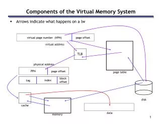
3 components for Virtual Reality (review) • Sensing system • Detection of motion (head, eyeball, trunk, upper limbs and lower limbs) in real 3D space and input to computer • Simulation system • Creation of virtual space, and calculation of motion of virtual objects and real-virtual matching • Display system (Realistic display) • Display of not only visual but aural, tactile and olfactory information, and stimulus of sense organs
The relationship among 3 components (review) real space virtual space Display system Simulation system Person Sensing system computer
Sensing system • What is done? and Where is it done? • Measurement of Where • Coordinates and direction in 3D space • 6 Degree Of Freedom : 6DOF • Coordinates: x, y, z • Direction : Euler angle (yaw, pitch, roll) • “Tracker” • Measurement of What • Form of hand or body and their action • Creation and display of their CG after the measurement • Input of the intention of operating object
Sensing system : Euler angle • Definition of the order of axis rotation • “yaw, pitch, roll” means : • 1st : z-axis, α[degree] • 2nd : y-axis, β[degree] • 3rd : x-axis, γ[degree] in the right figure
Sensing System : Euler angle (X,Y,Z):World coordinate system (x,y,z):Local coordinate system
Required condition of Tracker • Measurement of coordinates (x,y,z) and direction (yaw, pitch, roll), total 6DOF • 6DOF information can be measured in real time • The sampling rate is enough for representation of user’s natural action • The precision is less than one of sense of organ • The range where Tracker can measure 6DOF can cover the range of user’s action • Tracker doesn’t restrict user’s action and it should be free from environment
Sensing system : Tracker • Tracker by electromagnetic induction • Use of electromagnetic induction • 3 coils intersect perpendicularly each other • Transmitter (fixed) • Generation of changing Magnetic flux • Receiver (moving object) • Change of Linkage flux -> induced current in each of coils • Magnitude of induced currents is determined by position (x,y,z) and direction (pitch,yaw,roll) of the receiver. • 6DOF of the receiver (moving object) can be detected by the induced currents.
Sensing system : Tracker Induced voltage V=f (x,y,z,α,β,γ) depends on distance from transmitter and angle of receiver coil (amount of flux linkage) Receiver coil (x,y,z,α,β,γ) Generation and change of Electromagnetic field Orthogonal coil V=f (x,y,z,α,β,γ) V=f (x,y,z,α,β,γ) Transmitter coil (fixed in the space) 9 equation, 6 unknown information
Control unit drive circuit detector Sensing system : Tracker Magnetic field Receiver Transmitter (orthogonal coil) (orthogonal coil) Output of 6DOF of receiver (X、Y、Z、Roll、Yaw、Pitch)
Sensing system : Tracker • Advantages • High precision • Coordinate : a few [mm], Angle : less than 1[deg] • Small size and light weight • Not suffer from physical obstacles • Weak points • Narrow range of measurement, which depends on the size of transmitter • Suffer from magnetic material, for example, a desk made by steel • More the number of receiver is, less the sampling rate becomes
Sensing system : Tracker • 3SPACE SYSTEM (POLHEMUS Inc.) • Precision • position2.4 [mm] • angle 0.75 [degree] • Area • hemisphere whose radius is 76 [cm] • Data rate • 30pts/s (2receiver) ISOTRAKII
The distance is used as a radius Receive US Calculation of distance Angle of the Tracker can be detected Sensing system : TrackerTracker by ultrasound A A transmitter is on the cross point of 2 arcs. B Tracker 2 transmitter A transmitter is on the arc Measurement of B transmitter by the same matter Receiver (fixed)
Sensing system : TrackerTracker by ultrasound • 6DOF measurement by 3 transmitters and 3 receivers • Advantages • Easy for measurement • Not suffer from magnetic materials • Weak points • Error by a change of sound velocity • Suffer from the reflection and physical obstacles
Sensing system : TrackerTracker by ultrasound • Ivan Sutherland’s method • 3 transmitter on user’s helmet • 37, 38.6, 40.2kHz • 4 receivers at each corner of the ceiling • Continuous USs are transmitted, and separated after the measurement. • 12 patterns of phase shifts between transmitted USs and received USs can be used for position detection
Sensing system : TrackerTracker by ultrasound • InterSense, Inc.IS-900 • The wide range of tracking • 3m×3m~15m×15m • The Precision • coordinate4mm • angle 0.2~0.4 [degree] • The size of sensor • 3cm~4cm • Data rate180Hz
Sensing system : TrackerTracker by Optics • Markers emit by infrared rays and the markers are taken by high speed camera • Multiple camera and transmittance of infrared rays • High speed and high precision of measurement (6DOF in real time) can be realized • No restriction for user • No limitation of the number of marker
Sensing system : TrackerTracker by Optics • Vicon • Maximum 16million pixels,10-bit gray scale • Maximum shutter speed2000FPS • Maximum motion processing speed 120FPS • A small marker can cover the wide range and measure the information in detailed • Resolution less than 5mm in practical case http://crescentinc.co.jp/vicon
Sensing system : TrackerTracker by Optics • HoloStage, Immersive Virtual Environment in Tokai University
Sensing system : glove device • Input of user’s intention of manipulation of computer (virtual space manipulation) • Keyboard and mouse are not enough. • Data glove • Input of motion of hand and finger • Every joint has a sensor. • The sensor measures bent angle. • Precision is 0.5 [degree]. • The form of hand is prepared in CG.
Sensing system : glove devicebasic principles • Attach a sensor to hand and finger, their deformation are measured • Optical fiber method • The change of transmittance by the bent angle • VPL Inc,DataGlove, 1987 • Conductive ink with cloth method • The change of resistance by a bend of finger • Virtual Technologies Inc,CyberGlove
Sensing system : glove deviceexample of optical type • VPL Inc, DataGlove 1987 • 2 fibers for one finger • No.1 and No.2 joint of a finger are measured. • = 10DOF • The shape of a fiber is “U”. • LED -> fiber -> phototransistor • Approximation of the action by CG
Sensing system : glove deviceexample of conductive ink type • Conductive ink • Liquid with particle who has conductivity, for example, carbon • The resistance depends on the length of a sensor. • The length of a sensor depends on the bent angle. Short = low resistance Long = high resistance The bent angle sensor by conductive ink
Sensing system : glove deviceexample of conductive ink type • Immersion Inc, CyberGlove • The number of sensor:18 or 22 • 18 models • 2 sensor for each fingers, the root of thums, the bent angle and twist of wrist • 22 models • 18 models + 4 No.1 angles of each finger • precision:0.5 degree • Refresh rate :149 record/s