Download
1 / 37
410 likes | 656 Vues
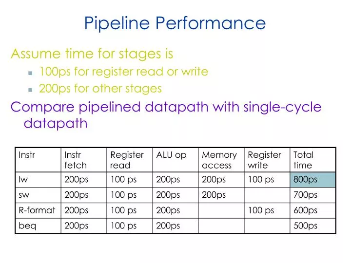
Pipeline Performance. Assume time for stages is 100ps for register read or write 200ps for other stages Compare pipelined datapath with single-cycle datapath. Pipeline Performance. Single-cycle (T c = 800ps). Pipelined (T c = 200ps). Pipeline Speedup. If all stages are balanced

E N D
Pipeline Performance Assume time for stages is • 100ps for register read or write • 200ps for other stages Compare pipelined datapath with single-cycle datapath
Pipeline Performance Single-cycle (Tc= 800ps) Pipelined (Tc= 200ps)
Pipeline Speedup • If all stages are balanced • i.e., all take the same time • Time between instructionspipelined= Time between instructionsnonpipelined Number of stages • If not balanced, speedup is less • Speedup due to increased throughput • Latency (time for each instruction) does not decrease
Pipelining and ISA Design • MIPS ISA designed for pipelining • All instructions are 32-bits • Easier to fetch and decode in one cycle • c.f. x86: 1- to 17-byte instructions • Few and regular instruction formats • Can decode and read registers in one step • Load/store addressing • Can calculate address in 3rd stage, access memory in 4th stage • Alignment of memory operands • Memory access takes only one cycle
Improving performance Two ideas for improving performance: Spilt each instruction into multiple steps, each taking 1 cycle steps: IF (instruction fetch), ID (instruction decode), EX (execute ALU operation), MEM (memory access), WB (register write-back) slow instructions take more cycles than fast instructions known as a multi-cycle implementation Crucial observation: each instruction uses only a portion of the datapath in each step can overlap instructions; each uses one portion of the datapath known as a pipelined implementation Examples of pipelining: any assembly process (cars, sandwiches), multiple loads of laundry (washer + dryer can be pipelined), etc. 5
Pipelining not just Multiprocessing Pipelining does involve parallel processing, but in a specific way Both multiprocessing and pipelining relate to the processing of multiple “things” using multiple “functional units” In multiprocessing, each thing is processed entirely by a single functional unit e.g. multiple lanes at the supermarket In pipelining, each thing is broken into a sequence of pieces, where each piece is handled by a different (specialized) functional unit e.g. checker vs. bagger Pipelining and multiprocessing are not mutually exclusive Modern processors do both, with multiple pipelines (e.g. superscalar) Pipelining is a general-purpose efficiency technique; used elsewhere in CS: Networking, I/O devices, server software architecture 6
While IF is executing, the rest of the data path is sitting idle… Instruction Fetch (IF) RegWrite MemToReg MemWrite Read address Instruction [31-0] I [25 - 21] Read register 1 Read data 1 ALU Read address Read data 1 M u x 0 I [20 - 16] Zero Read register 2 Instruction memory Read data 2 0 M u x 1 Result Write address 0 M u x 1 Write register Data memory Write data Registers I [15 - 11] ALUOp Write data MemRead ALUSrc RegDst I [15 - 0] Sign extend 7
Then while ID is executing, the IF-related portion becomes idle… Instruction Decode (ID) RegWrite MemToReg MemWrite Read address Instruction [31-0] I [25 - 21] Read register 1 Read data 1 ALU Read address Read data 1 M u x 0 I [20 - 16] Zero Read register 2 Instruction memory Read data 2 0 M u x 1 Result Write address 0 M u x 1 Write register Data memory Write data Registers I [15 - 11] ALUOp Write data MemRead ALUSrc RegDst I [15 - 0] Sign extend 8
..and so on for the EX portion… Execute (EX) RegWrite MemToReg MemWrite Read address Instruction [31-0] I [25 - 21] Read register 1 Read data 1 ALU Read address Read data 1 M u x 0 I [20 - 16] Zero Read register 2 Instruction memory Read data 2 0 M u x 1 Result Write address 0 M u x 1 Write register Data memory Write data Registers I [15 - 11] ALUOp Write data MemRead ALUSrc RegDst I [15 - 0] Sign extend 9
…the MEM portion… Memory (MEM) RegWrite MemToReg MemWrite Read address Instruction [31-0] I [25 - 21] Read register 1 Read data 1 ALU Read address Read data 1 M u x 0 I [20 - 16] Zero Read register 2 Instruction memory Read data 2 0 M u x 1 Result Write address 0 M u x 1 Write register Data memory Write data Registers I [15 - 11] ALUOp Write data MemRead ALUSrc RegDst I [15 - 0] Sign extend 10
…and the WB portion Write back (WB) RegWrite MemToReg MemWrite Read address Instruction [31-0] I [25 - 21] Read register 1 Read data 1 ALU Read address Read data 1 M u x 0 I [20 - 16] Zero Read register 2 Instruction memory Read data 2 0 M u x 1 Result Write address 0 M u x 1 Write register Data memory Write data Registers I [15 - 11] ALUOp Write data MemRead ALUSrc RegDst I [15 - 0] Sign extend 11
Decoding and fetching together Why don’t we go ahead and fetch the next instruction while we’re decoding the first one? RegWrite MemToReg MemWrite Read address Instruction [31-0] I [25 - 21] Read register 1 Read data 1 ALU Read address Read data 1 M u x 0 I [20 - 16] Zero Read register 2 Instruction memory Read data 2 0 M u x 1 Result Write address 0 M u x 1 Write register Data memory Write data Registers I [15 - 11] ALUOp Write data MemRead ALUSrc RegDst I [15 - 0] Sign extend Fetch 2nd Decode 1st instruction 12
Executing, decoding and fetching Similarly, once the first instruction enters its Execute stage, we can go ahead and decode the second instruction. But now the instruction memory is free again, so we can fetch the third instruction! RegWrite MemToReg MemWrite Read address Instruction [31-0] I [25 - 21] Read register 1 Read data 1 ALU Read address Read data 1 M u x 0 I [20 - 16] Zero Read register 2 Instruction memory Read data 2 0 M u x 1 Result Write address 0 M u x 1 Write register Data memory Write data Registers I [15 - 11] ALUOp Write data MemRead ALUSrc RegDst I [15 - 0] Sign extend Fetch 3rd Execute 1st Decode 2nd 13
Break datapath into 5 stages Each stage has its own functional units Full pipeline the datapath is simultaneously working on 5 instructions! IF WB ID EXE MEM RegWrite MemToReg MemWrite Read address Instruction [31-0] I [25 - 21] Read register 1 Read data 1 ALU Read address Read data 1 M u x 0 I [20 - 16] Zero Read register 2 Instruction memory Read data 2 0 M u x 1 Result Write address 0 M u x 1 Write register Data memory Write data Registers I [15 - 11] ALUOp Write data MemRead ALUSrc RegDst I [15 - 0] Sign extend newest oldest 14
A pipeline diagram A pipeline diagram shows the execution of a series of instructions The instruction sequence is shown vertically, from top to bottom Clock cycles are shown horizontally, from left to right Each instruction is divided into its component stages This clearly indicates the overlapping of instructions. For example, there are three instructions active in the third cycle above. The “lw” instruction is in its Execute stage. Simultaneously, the “sub” is in its Instruction Decode stage. Also, the “and” instruction is just being fetched. 15
Pipeline terminology The pipeline depth is the number of stages—in this case, five In the first four cycles here, the pipeline is filling, since there are unused functional units In cycle 5, the pipeline is full. Five instructions are being executed simultaneously, so all hardware units are in use In cycles 6-9, the pipeline is emptying filling full emptying 16
Pipelining Performance Execution time on ideal pipeline: time to fill the pipeline + one cycle per instruction How long for N instructions? k 1 + N, where k = pipeline depth Alternate way of arriving at this formula: k cycles for the first instruction, plus 1 for each of the remaining N 1 instructions. Compare this pipelined implementation (2ns clock period) vs. a single cycle implementation (8ns clock period). How much faster is pipelining for N=1000 ? filling 17
Pipeline Datapath: Resource Requirements We need to perform several operations in the same cycle. Increment the PC and add registers at the same time. Fetch one instruction while another one reads or writes data. What does that mean for our hardware? Separate ADDER and ALU Two memories (instruction memory and data memory) 18
Single-cycle datapath, slightly rearranged Add Add 1 0 PCSrc 4 P C Shift left 2 RegWrite Read register 1 Read data 1 MemWrite ALU Read address Instruction [31-0] Zero Read register 2 Read data 2 0 1 Result Address Write register Data memory Instruction memory MemToReg Registers ALUOp Write data ALUSrc Write data Read data 1 0 Instr [15 - 0] Sign extend RegDst MemRead Instr [20 - 16] 0 1 Instr [15 - 11] 19
Pipeline registers In pipelining, we divide instruction execution into multiple cycles IF ID EX MEM WB Information computed during one cycle may be needed in a later cycle: Instruction read in IF stage determines which registers are fetched in ID stage, what immediate is used for EX stage, and what destination register is for WB Register values read in ID are used in EX and/or MEM stages ALU output produced in EX is an effective address for MEM or a result for WB A lot of information to save! Saved in intermediate registers called pipeline registers The registers are named for the stages they connect: IF/ID ID/EX EX/MEM MEM/WB No register is needed after the WB stage, because after WB the instruction is done 20
Pipelined datapath 0 1 Add Add Shift left 2 1 0 PCSrc 4 IF/ID ID/EX EX/MEM MEM/WB P C RegWrite Read register 1 Read data 1 MemWrite ALU Read address Instruction [31-0] Zero Read register 2 Read data 2 0 1 Result Address Write register Data memory Instruction memory MemToReg Registers ALUOp Write data ALUSrc Write data Read data 1 0 Instr [15 - 0] Sign extend RegDst MemRead Instr [20 - 16] Instr [15 - 11] 21
Propagating values forward Data values required later propagated through the pipeline registers The most extreme example is the destination register (rd or rt) It is retrieved in IF, but isn’t updated until the WB Thus, it must be passed through all pipeline stages, as shown in red on the next slide Notice that we can’t keep a single “instruction register,” because the pipelined machine needs to fetch a new instruction every clock cycle 22
The destination register Add Add Shift left 2 1 0 PCSrc 4 IF/ID ID/EX EX/MEM MEM/WB P C RegWrite Read register 1 Read data 1 MemWrite ALU Read address Instruction [31-0] Zero Read register 2 Read data 2 0 1 Result Address Write register Data memory Instruction memory MemToReg Registers ALUOp Write data ALUSrc Write data Read data 1 0 Instr [15 - 0] Sign extend RegDst MemRead Instr [20 - 16] 0 1 Instr [15 - 11] 23
What about control signals? Control signals generated similar to the single-cycle processor in the ID stage, the processor decodes the instruction fetched in IF and produces the appropriate control values Some of the control signals will not be needed until later stages These signals must be propagated through the pipeline until they reach the appropriate stage We just pass them in the pipeline registers, along with the data Control signals can be categorized by the pipeline stage that uses them 24
Pipelined data path and control 0 1 Add Add Shift left 2 1 0 ID/EX EX/MEM WB PCSrc WB Control MEM/WB M 4 IF/ID EX M WB P C RegWrite Read register 1 Read data 1 MemWrite ALU Read address Instruction [31-0] Zero Read register 2 Read data 2 0 1 Result Address Write register Data memory Instruction memory MemToReg Registers ALUOp Write data ALUSrc Write data Read data 1 0 Instr [15 - 0] Sign extend RegDst MemRead Instr [20 - 16] Instr [15 - 11] 25
Here’s a sample sequence of instructions to execute 1000: lw $8, 4($29) 1004: sub $2, $4, $5 1008: and $9, $10, $11 1012: or $16, $17, $18 1016: add $13, $14, $0 We’ll make some assumptions, just so we can show actual data values: Each register contains its number plus 100. For instance, register $8 contains 108, register $29 contains 129, etc. Every data memory location contains 99 Our pipeline diagrams will follow some conventions: An X indicates values that aren’t important, like the constant field of an R-type instruction Question marks ??? indicate values we don’t know, usually resulting from instructions coming before and after the ones in our example An example execution sequence addresses in decimal 26
Cycle 1 (filling) 0 1 1 0 ID/EX EX/MEM WB Add Add PCSrc Control MEM/WB M WB Shift left 2 4 IF/ID EX M WB 1004 P C RegWrite (?) ??? ??? ??? Read register 1 Read data 1 1000 MemWrite (?) ALU Read address Instruction [31-0] Zero ??? ??? Read register 2 Read data 2 ??? ??? 0 1 Result Address ??? Write register MemToReg (?) ??? Data memory Instruction memory Registers ALUOp (???) ??? Write data ??? ??? ALUSrc (?) Write data Read data 1 0 Sign extend ??? ??? RegDst (?) ??? MemRead (?) ??? ??? ??? ??? ??? ??? ??? ??? IF: lw $8, 4($29) ID: ??? EX: ??? MEM: ??? WB: ??? 27
Cycle 2 1 0 0 1 ID/EX EX/MEM WB Add Add PCSrc Control MEM/WB M WB Shift left 2 4 IF/ID EX M WB 1008 P C RegWrite (?) 129 29 ??? Read register 1 Read data 1 1004 MemWrite (?) ALU Read address Instruction [31-0] Zero X X ??? Read register 2 Read data 2 ??? 0 1 Result Address ??? Write register MemToReg (?) ??? Data memory Instruction memory Registers ALUOp (???) ??? Write data ??? ??? ALUSrc (?) Write data Read data 1 0 4 Sign extend ??? RegDst (?) ??? MemRead (?) 8 ??? ??? ??? ??? X ??? ??? IF: sub $2, $4, $5 ID: lw $8, 4($29) EX: ??? MEM: ??? WB: ??? 28
Cycle 3 0 1 1 0 ID/EX EX/MEM WB Add Add PCSrc Control MEM/WB M WB Shift left 2 4 IF/ID EX M WB 1012 P C RegWrite (?) 104 4 129 Read register 1 Read data 1 1008 MemWrite (?) ALU Read address Instruction [31-0] Zero 5 X 10⁵ Read register 2 Read data 2 ??? 0 1 Result Address 4 133 Write register MemToReg (?) ??? Data memory Instruction memory Registers ALUOp (add) ??? Write data ??? ??? ALUSrc (1) Write data Read data 1 0 X Sign extend 4 RegDst (0) MemRead (?) ??? X 8 ??? ??? 8 2 X ??? IF: and $9, $10, $11 ID: sub $2, $4, $5 EX: lw $8, 4($29) MEM: ??? WB: ??? 29
Cycle 4 1 0 0 1 ID/EX EX/MEM WB Add Add PCSrc Control MEM/WB M WB Shift left 2 4 IF/ID EX M WB 1016 P C RegWrite (?) 110 10 104 Read register 1 Read data 1 1012 MemWrite (0) ALU Read address Instruction [31-0] Zero 11 105 111 Read register 2 Read data 2 133 0 1 Result Address –1 Write register MemToReg (?) ??? Data memory Instruction memory Registers ALUOp (sub) ??? Write data 99 ??? ALUSrc (0) Write data Read data X 1 0 X Sign extend X RegDst (1) ??? MemRead (1) X X 2 8 ??? 9 2 ??? IF: or $16, $17, $18 ID: and $9, $10, $11 EX: sub $2, $4, $5 MEM: lw $8, 4($29) WB: ??? 30
Cycle 5 (full) 1 0 0 1 ID/EX EX/MEM WB Add Add PCSrc Control MEM/WB M WB Shift left 2 4 IF/ID EX M WB 1020 P C RegWrite (1) 117 17 110 Read register 1 Read data 1 1016 MemWrite (0) ALU Read address Instruction [31-0] Zero 18 111 118 Read register 2 Read data 2 -1 0 1 Result Address 8 Write register MemToReg (1) 110 Data memory Instruction memory Registers ALUOp (and) 99 Write data X 99 ALUSrc (0) Write data Read data 105 1 0 X Sign extend X RegDst (1) 133 MemRead (0) X X 9 2 8 16 9 99 IF: add $13, $14, $0 ID: or $16, $17, $18 EX: and $9, $10, $11 MEM: sub $2, $4, $5 WB: lw $8, 4($29) 31
Cycle 6 (emptying) 1 0 0 1 ID/EX EX/MEM WB Add Add PCSrc Control MEM/WB M WB Shift left 2 4 IF/ID EX M WB ??? P C RegWrite (1) 114 14 117 Read register 1 Read data 1 1020 MemWrite (0) ALU Read address Instruction [31-0] Zero 0 118 0 Read register 2 Read data 2 110 0 1 Result Address 119 2 Write register MemToReg (0) Data memory Instruction memory Registers ALUOp (or) -1 Write data X X ALUSrc (0) Write data Read data 111 1 0 X Sign extend X RegDst (1) -1 MemRead (0) X X 16 9 2 13 16 -1 IF: ??? ID: add $13, $14, $0 EX: or $16, $17, $18 MEM: and $9, $10, $11 WB: sub $2, $4, $5 32
Cycle 7 1 0 0 1 ID/EX EX/MEM WB Add Add PCSrc Control MEM/WB M WB Shift left 2 4 IF/ID EX M WB ??? P C RegWrite (1) ??? ??? 114 Read register 1 Read data 1 ??? MemWrite (0) ALU Read address Instruction [31-0] Zero ??? 0 ??? Read register 2 Read data 2 119 0 1 Result Address 9 Write register MemToReg (0) 114 Data memory Instruction memory Registers ALUOp (add) 110 Write data X X ALUSrc (0) Write data Read data 118 1 0 ??? Sign extend X RegDst (1) MemRead (0) 110 ??? X 13 16 9 ??? 13 110 IF: ??? ID: ??? EX: add $13, $14, $0 MEM: or $16, $17, $18 WB: and $9, $10, $11 33
Cycle 8 0 1 1 0 ID/EX EX/MEM WB Add Add PCSrc Control MEM/WB M WB Shift left 2 4 IF/ID EX M WB ??? P C RegWrite (1) ??? ??? ??? Read register 1 Read data 1 ??? MemWrite (0) ALU Read address Instruction [31-0] Zero ??? ??? ??? Read register 2 Read data 2 114 0 1 Result Address 16 Write register MemToReg (0) ??? Data memory Instruction memory Registers ALUOp (???) 119 Write data X X ALUSrc (?) Write data Read data 0 1 0 ??? Sign extend ??? RegDst (?) MemRead (0) 119 ??? ??? 13 16 ??? ??? ??? 119 IF: ??? ID: ??? EX: ??? MEM: add $13, $14, $0 WB: or $16, $17, $18 34
Cycle 9 0 1 1 0 ID/EX EX/MEM WB Add Add PCSrc Control MEM/WB M WB Shift left 2 4 IF/ID EX M WB ??? P C RegWrite (1) ??? ??? ??? Read register 1 Read data 1 ??? MemWrite (?) ALU Read address Instruction [31-0] Zero ??? ??? ??? Read register 2 Read data 2 ??? 0 1 Result Address 13 Write register MemToReg (0) ??? Data memory Instruction memory Registers ALUOp (???) 114 Write data X X ALUSrc (?) Write data Read data ? 1 0 ??? Sign extend ??? RegDst (?) 114 MemRead (?) ??? ??? ??? 13 ??? ??? ??? 114 IF: ??? ID: ??? EX: ??? MEM: ??? WB: add $13, $14, $0 35
That’s a lot of diagrams there Compare the last few slides with the pipeline diagram above You can see how instruction executions are overlapped Each functional unit is used by a different instruction in each cycle The pipeline registers save control and data values generated in previous clock cycles for later use When the pipeline is full in clock cycle 5, all of the hardware units are utilized. This is the ideal situation, and what makes pipelined processors so fast 36
Note how everything goes left to right, except 0 1 Add Add Shift left 2 1 0 PCSrc 4 IF/ID ID/EX EX/MEM MEM/WB P C RegWrite Read register 1 Read data 1 MemWrite ALU Read address Instruction [31-0] Zero Read register 2 Read data 2 0 1 Result Address Write register Data memory Instruction memory MemToReg Registers ALUOp Write data ALUSrc Write data Read data 1 0 Instr [15 - 0] Sign extend RegDst MemRead Instr [20 - 16] Instr [15 - 11] 37