Download
1 / 33
330 likes | 497 Vues
STAR Heavy Flavor Tracker Upgrade --PXL Detector. Xiangming Sun Lawrence Berkeley National Lab. L. Greiner, H. Matis J. Schambach T. Stezelberger M. Szelezniak C. Vu H. Wieman … …. Outline. Heavy Flavor Tracker upgrade in STAR at RHIC PXL detector architecture

E N D
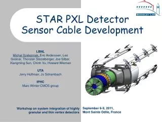
STAR Heavy Flavor Tracker Upgrade --PXL Detector Xiangming Sun Lawrence Berkeley National Lab L. Greiner, H. Matis J. Schambach T. Stezelberger M. Szelezniak C. Vu H. Wieman … …
Outline • Heavy Flavor Tracker upgrade in STAR at RHIC • PXL detector architecture • Cooling and vibration testing • Monolithic Active Pixel Sensor for PXL • PXL Readout Electronics • Summary
STAR Detector at RHIC STAR(the solenoidal tracker at RHIC ) is one of Detector at RHIC. It specializes in tracking the thousands of particles produced by each ion collision RHIC (Relativistic heavy ion collider) Brookhaven National Lab http://www.bnl.gov/rhic/
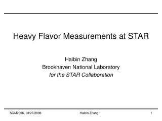
PXL in Inner Detector Upgrades TPC – Time Projection Chamber (main tracking detector in STAR) HFT – Heavy Flavor Tracker • SSD – Silicon Strip Detector • r = 22 cm • IST – Inner Silicon Tracker • r = 14 cm • PXL – Pixel Detector • r = 2.5, 8 cm We track inward from the TPC with graded resolution: ~1mm ~300µm ~250µm <30µm vertex TPC SSD IST PXL
PXL Detector 2 layers: 2.5,8 cm 10 sectors 1+3 ladders/ sector Ladder with 10 MAPS sensors (~ 2×2 cm each)
PXL Mechanical Construction http://rnc.lbl.gov/hft/hardware/docs/ultimate/HFT_Mechanics_20110428.pptx
Some PXL Parameters critical and difficult
Association Rate vs Pointing Resolution and Hit Density Association rate: associating hits to tracks from outer detector Nhits per sensor=500 for 200us integration time Pointing resolution=250um Association rate=67%
Cooling and vibration testing • Sensor: 170 mW/cm2→ 270 W for PXL sensors • 2 W/drivers/cable → 80 W for PXL drivers Silicon heater on 1 sector PCB heaters on 9 sectors
Cooling Tests at ~360 W – IR Images From infra-red camera Air 13.8 m/s Hot spots ~37 °C Air 10.1 m/s Hot spots ~41 °C Air 4.7 m/s Hot spots ~48 °C Air temperature ~27 °C
Vibrations Caused by Airflow Using capacitance sensor to measure vibration Beginning of the driver section (Supported end) End of sensor section (Unsupported end)
Monolithic Active Pixel Sensors MAPS pixel cross-section (not to scale) • IPHC-DRS (former IRES/LEPSI) proposed using MAPS for high energy physics in 1999 • Standard commercial CMOS technology • Sensor and signal processing are integrated in the same silicon wafer • Proven thinning to 50 micron • Signal is created in the low-doped epitaxial layer (typically ~10-15 μm) → MIP • signal is limited to <1000 electrons • Charge collection is mainly through diffusion (~100 ns), reflective boundaries at p-epi and substrate → cluster size is about ~10 pixels (20-30 μm pixel pitch) • Room temperature operation
PXL Sensor generation and RDO attributes CDS Data sparsification readout to DAQ Pixel Sensors Disc. 3 generation program with highly coupled sensor and readout development Complementary detector readout digital signals analog signals digital ADC CDS analog MimoSTAR sensors 4 ms integration time 1 2 Phase-1 sensors 640 μs integration time 3 PXL final sensors (Ultimate) < 200 μs integration time Sensor and RDO Development Path
From Analog to Binary Readout Analog readout – simpler architecture but slower readout Digital readout – offers increased speed but requires on-chip discriminators or ADCs and increased S/N for on-chip signal processing
MAPS Integration Time = Readout Time • Column parallel readout architecture • All columns readout in parallel and then multiplexed to one output • Integration time = column readout time • Integration time =200 us • Typical sensor readout • “rolling shutter” mode. • Integration time = array readout time
PXL Readout Schematics i/o USB ADC SIU FPGA DAQ RDO PCs SRAM Power Supplies Control PCs Trigger Ladder x 4 RDO board x 1 fiber Unified Development Platform Sensor testing Probe testing LU prot. power Black – cfg, ctl, clk. path Blue – data path Red – power / gnd path Green – testing path MTB x 1
PXL Readout Electronics 6 m (24 AWG TP) 2 m (42 AWG TP) Mass termination board + latch up protected power daughtercard ← Front Back ↓ 100 m (fiber optic) RDO PC with DDL link to RDO board RDO motherboard + Xilinx Virtex-5 Dev Board • 4 ladders per sector • 1 Mass Termination Board (MTB) per sector • 1 sector per RDO board • 10 RDO boards in the PIXEL system
Sensors / Ladders / Sectors (interaction point) RDO Boards RDO System Design – Physical Layout 1-2 m Low mass twisted pair LU Protected Regulators, Mass cable termination Platform 30 m Power Supplies 6 m - twisted pair 30 m 100 m - Fiber optic Control PCs 30 m USB DAQ Room DAQ PCs 400MB/s (Low Rad Area)
Firmware Structure 19 sensor Xilinx Virtex-5 Dev Board DDL/USB PC
IODelay for Digital Data Alignment 800 channels, 160 MHz digital signals pass 8 meters before arriving FPGA. digital need to be aligned in FPGA end. Solution: FPGA iodelay function • Status • Data Path Architecture Validated • Measured BER (bit error rate) of < 10-14
System Control Hex file Command generator: command.exe USB upload download_data_block_to_FEE 0x0402fffd 0x1d82ff3f 0x1502ffcf 0x2642ffff 0x2642fdff 0x2202feff 0x0c03fff0 0x1547ffff 0x1547ffff 0x1547ffff 0x1547ffdf 0x0cc7ffff 0x0cc7ffff …………. USB download rorc_receive DAQ PC Control PC
Summary Our current status: Layer thickness X/X0=0.37% Air speed ~10 m/s Senor temp arise 14 °C Vibration <8 um rms The integration time 186 us Readout Electronics prototyped and works as required The PXL is expected to be fully installed in 2013 for RHIC Run14
Activity in Wuhan CCNU plans to in study Pixel sensor. (Nu Xu proposed) Pixel sensor in high energy physics is a good opportunity for CCNU to start Try to be familiar with IC design environment(2 student) Try to be familiar with XFAB technology 0.35 MPW in May 20 in XFAB.
PXL Detector Cabling and cooling infrastructure New beryllium beam pipe (800 µm thick, r = 2.5 cm) Mechanical support with kinematic mounts 2 layers 10 sectors 3+1 ladders/ sector Ladder with 10 MAPS sensors (~ 2×2 cm each)
Radiation Environment Direct measurement has not been done so far. • Based on estimates (http://rnc.lbl.gov/~wieman/radiation dose strausoct 2007 HW.ppt) and TLD projection. • For the radius of 2.5 cm: • Ionizing radiation: • Total dose: 155 kRad • TLD projection: 300 kRad • Non-ionizing radiation • average pion count for 1 Yr: 3x1012 cm-2 • TLD projection (pion assumption): 12x1012 cm-2
Ionizing Radiation Tolerance MIMOSA-22 Testing in 10 KeV X-Rays in Lab MIMOSA-22ter • Signal/noise ratio >=20 after 300 kRad Ionizing radiation (300 e+e- pairs) • Non-ionizing radiation is under investigation
The Heavy Flavor Tracker (HFT) is an upgrade project for the STAR detector at RHIC, It will allow the topological reconstructions of the heavy flavor hadrons via their hadronic decays . The HFT consists of three coaxial detectors: SSD(Silicon Strip Detector), IST(Intermediate Si-Tracker) and PIXEL(a pixel detector). The PIXEL is the inner-most and highest precision detector in HFT. The sensor chip we use to build PIXEL is developed in Monolithic Active Pixel Sensor(MAPS) technology. Each sensor has 1024X1188 pixels with 18.4 micron pitch and 50 micron thickness. The integration time is 200 us. Correlated double sampling (CDS) and digitization are performed on the sensor chip. The readout electronics is designed to handle 400 sensors which are grouped in 10 sectors. In this talk, we discuss the relation between the physics goals and sensor characteristics, such as pixel size, sensor thickness, integration time, radiation tolerance and power consumption. We introduce the on-chip electronics design to perform CDS and digitization. We also show the readout electronics designed to handle R&D tests and physics data acquisition. The PIXEL is expected to be fully installed in 2014 for RHIC Run14
Probe Tests • Status • Automated and scripted system for sensor testing is in place. • Vacuum chuck for handling up to twenty 50 μm thick sensors is being tested • Ongoing sensor testing • Sensors designed with dedicated probe pads in the sensor pad ring. • 13 full-thickness, diced sensors probe tested. • Up to 3 probe tests on a sensor. • We will begin testing thinned sensors within the next few days Phase-1 discriminator transfer functions ƒ(threshold voltage) observed on two of the probed sensors : 30 μm additional lowering of probe pins Initial testing with ~75 μm travel past touchdown
Cooling tests at ~360 W • Initially: 100 mW/cm2→ 160 W for PXL sensors • Updated: x1.7 → 270 W for PXL sensor • 2 W/drivers/cable → 80 W for PXL drivers
MAPS @ Institut Pluridisciplinaire Hubert Curien • IPHC-DRS (former IRES/LEPSI) proposed using MAPS for high energy physics in 1999 • CMOS & ILC group today • 6 physists • 9 microcircuit designers • 6 test engineers • 7 PhD students CNRS - IPHC, Strasbourg-Cronenbourg • More than 30 prototypes developed • several pixel sizes and architectures (simple 3-transistor cells, pixels with in-pixel amplifiers and CDS processing) • different readout strategies (sensors operated in current and voltage mode, analog and digital output) • Large variety of prototype sizes (from several hundreds of pixels up to 1M pixel prototype with full-reticule size) MIMOSA (Minimum Ionizing particle MOS Active sensor)
PXL Hardware Architecture Ladder RDO motherboard Mass Termination Board
PXL Detector Mechanical support with kinematic mounts 2 layers: 2.5,8 cm 10 sectors 1+3 ladders/ sector Ladder with 10 MAPS sensors (~ 2×2 cm each)