Download
1 / 32
320 likes | 636 Vues
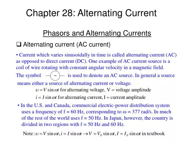
Chapter 28: Alternating Current. Alternating current (AC current). Current which varies sinusoidally in time is called alternating current (AC) as opposed to direct current (DC). One example of AC current source is a coil of wire rotating with constant angular velocity in a magnetic field.

E N D
Chapter 28: Alternating Current • Alternating current (AC current) • Current which varies sinusoidally in time is called alternating current (AC) as opposed to direct current (DC). One example of AC current source is a coil of wire rotating with constant angular velocity in a magnetic field. The symbol ~ is used to denote an AC source. In general a source Phasors and Alternating Currents means either a source of alternating current or voltage. • In the U.S. and Canada, commercial electric-power distribution system • uses a frequency of f = 60 Hz, corresponding to w = 377 rad/s. In much • of the rest of the world uses f = 50 Hz. In Japan, however, the country is • divided in two regions with f = 50 Hz and 60 Hz.
Phasors and Alternating Currents • Phasors w phasor • A convenient way to express a quantity • varying sinusoidally with time is by • a phasor in phasor diagram as shown. IP I=IP sin wt wt • Rectifier and rectified current O - + + -
Phasors and Alternating Currents • Rectifier and rectified current (cont’d)
Phasors and Alternating Currents • Root-mean-square current and voltage • Root-mean-square current of a sinusoidal current time averaged • Root-mean-square voltage of a sinusoidal voltage For 120-volt AC, V=170 V.
R I R e ~ I V R R 0 0 0 0 t t Reluctance • Resistance, inductance, capacitance and reactance • Resistor in an AC circuit Given: Þ Voltage across R in phase with current through R I IR VR wt uR At time t I=em/R
L e ~ IL VL 0 0 0 0 t t Reluctance • Resistance, inductance, capacitance and reactance • Inductor in an AC circuit Given: I Þ L Þ Voltage across L leads current through L by one-quarter cycle (90°). I IL e VL em wt I=em/(wL) At time t
C I e C ~ IC VC 0 0 t 0 t 0 Reluctance • Resistance, inductance, capacitance and reactance • Capacitor in an AC circuit Given: Þ Þ Voltage across C lags current through C by one-quarter cycle (90°). I IC wt em e wt VC I=wCem At time t
XL XC reactance Reluctance • LRC series circuit and reluctance LRC circuit summary Given: Assume the solution for current: (See derivation later) amplitude
Reluctance • LRC series circuit and reluctance (cont’d) What is reactance? f=w/2p You can think of it as a frequency-dependent resistance. For high ω, χC~0 - Capacitor looks like a wire (“short”) For low ω, χC∞ - Capacitor looks like a break For low ω, χL~0 - Inductor looks like a wire (“short”) For high ω, χL∞ - Inductor looks like a break (inductors resist change in current)
Given: R • Assume: Þ C L e ~ Þ w I w L m f e m f f I m I R C w m LRC Circuits • LRC series circuit (cont’d) amplitude This picture corresponds to a snapshot at t=0. The projections of these phasors along the vertical axis are the actual values of the voltages at the given time. Im
R C L e ~ -φ LRC Circuits • LRC series circuit (cont’d) Problem: Given Vdrive = εm sin ωt, find VR, VL, VC, IR, IL, IC • Strategy: • Draw Vdrive phasor at t=0 • Guess iR phasor • Since VR = iR R, this is also the direction for the VR phasor. -f f (No L or C → f = 0) • Realize that due to Kirchhoff’s current law, iL = iC = iR (i.e., the same current flows through each).
VL= I XL -φ VR = I R LRC Circuits • LRC series circuit (cont’d) • The inductor current IL always lags VL draw VL 90˚ further counterclockwise. • The capacitor voltage VC always lags IC draw VC 90˚ further clockwise. -f VC = I XC The lengths of the phasors depend on R, L, C, and ω. The relative orientation of the VR, VL, and VC phasors is always the way we have drawn it. f is determined such that VR + VL + VC = ε (Kirchhoff’s voltage rule) These are added like vectors.
y Vout x ε ~ y IR x ε VC LRC Circuits • Phasor diagrams for LRC circuits: Example amplitude of current
Vout High-pass filter Note: this is ω, ~ LRC Circuits • Filters : Example Ex.: C = 1 μF, R = 1Ω
Vout Vout ~ ~ ~ LRC Circuits • Filters High- pass filter ω=0 No current Vout ≈ 0 ω=∞ Capacitor ~ wire Vout ≈ ε ω = ∞ No current Vout ≈ 0 ω = 0 Inductor ~ wire Vout ≈ ε Low- pass filter ω = 0 No current because of capacitor ω = ∞ No current because of inductor (Conceptual sketch only) Band-pass filter
I X m L I R I (X -X ) m m L C f e m Þ f f e f m I X I R m C m LRC Circuits • Phasor diagrams for LRC circuits: Example 2 Reluctance for inductor Reluctance for capacitor amplitude ß Impedance Z
X I m L y em f x f f I X I R m C ImXL m em f ImR | f | ImXC “Full Phasor Diagram” “Impedance Triangle” LRC Circuits • Phasor diagrams for LRC circuits: Tips • This phasor diagram was drawn as a snapshot of time t=0 with the voltages being given as the projections along the y-axis. f • Sometimes, in working problems, it is easier to draw the diagram at a time when the current is along the x-axis (when I=0). f f From this diagram, we can also create a triangle which allows us to calculate the impedance Z: f f
R C L e ~ Resonance in Alternating Current Circuits • Resonance For fixed R, C, L the current Im will be a maximum at the resonant frequency w0 which makes the impedance Z purely resistive. i.e.: reaches a maximum when: X X = L C This condition is obtained when: resonance frequency Þ • Note that this resonant frequency is identical to the natural frequency of the LC circuit by itself! • At this frequency, the current and the driving voltage are in phase!
XL e m Z R 0 R=Ro XL - XC Im f R R=2Ro 0 2wo 0 XC w Resonance in Alternating Current Circuits • Resonance (cont’d) e = f m I cos m R Plot the current versus w, the frequency of the voltage source: →
R C L e ~ Resonance in Alternating Current Circuits • Resonance (cont’d) On Resonance: f=0 and Z=R On resonance, the voltage across the reactive elements is amplified by Q! Necessary to pick up weak radio signals, cell phone transmissions, etc.
Power in Alternating Current Circuits • Power • The instantaneous power (for some frequency, w) delivered at time t is given by: • The most useful quantity to consider here is not the instantaneous power but rather the average power delivered in a cycle. • To evaluate the average on the right, we first expand the sin(wt-f) term.
+1 sinwtcoswt (Product of even and odd function = 0) 0 -1 2p 0 w t +1 sin2wt 1/2 0 0 -1 2p 0 w t Power in Alternating Current Circuits • Power • Expanding, • Taking the averages, • Generally: • Putting it all back together again,
Power delivered depends on the phase, f, the “power factor” Phase depends on the values of L, C, R, and w Therefore... Power in Alternating Current Circuits • Power This result is often rewritten in terms of rms values:
Power in Alternating Current Circuits • Power Power, as well as current, peaks at w = w0. The sharpness of the resonance depends on the values of the components. Recall: We can write this in the following manner (which we won’t try to prove): …introducing the curious factors Q and x...
A parameter “Q” is often defined to describe the sharpness of resonance peaks in both mechanical and electrical oscillating systems. “Q” is defined as Resonance in Alternating Current Circuits • Power and resonance where Umax is max energy stored in the system and DU is the energy dissipated in one cycle For RLC circuit, Umax is Losses only come from R: period This gives And for completeness, note
Q=3 e 2 rms R 0 FWHM R=Ro <P> R=2Ro 0 0 2wo w Resonance in Alternating Current Circuits • Power and resonance For Q > few, • FWHM • Full Width at Half Maximum • Q • Quality of the peak • Higher Q = sharper peak = better quality
iron ~ V1 e V2 N N 1 2 (secondary) (primary) Transformers • Transformers • AC voltages can be stepped up or stepped down by the use of transformers. The AC current in the primary circuit creates a time-varying magnetic field in the iron This induces an emf on the secondary windings due to the mutual inductance of the two sets of coils. • The iron is used to maximize the mutual inductance. We assume that the entire flux produced by each turn of the primary is trapped in the iron.
iron ~ V e V 1 2 N N 1 2 (secondary) (primary) Transformers • Ideal transformer without a load Nothing connected on secondary No resistance losses All flux contained in iron The primary circuit is just an AC voltage source in series with an inductor. The change in flux produced in each turn is given by: • The change in flux per turn in the secondary • coil is the same as the change in flux per turn in the primary coil (ideal case). • The induced voltage appearing across the secondary coil is given by: • Therefore, • N2 > N1 secondary V2 is larger than primary V1 (step-up) • N1 > N2 secondary V2 is smaller than primary V1 (step-down) • Note: “no load” means no current in secondary. The primary current, • termed “the magnetizing current” is small!
Transformers • Ideal transformer with a load What happens when we connect a resistive load to the secondary coil? Changing flux produced by primary coil induces an emf in secondary which produces current I2 iron R V e V ~ 1 2 N N 1 2 (secondary) (primary) • This current produces a flux in the secondary coil • µ N2I2, which opposes the change in the original • flux -- Lenz’s law • This induced changing flux appears in the primary • circuit as well; the sense of it is to reduce the emf in • the primary, to “fight” the voltage source. However, • V1 is assumed to be a voltage source. Therefore, there • must be an increased current I1 (supplied by the voltage • source) in the primary which produces a flux µ N1I1 • which exactly cancels the flux produced by I2.
iron R V e V ~ 1 2 N N 1 2 (secondary) (primary) = = The primary circuit has to drive the resistanceRof the secondary. Transformers • Ideal transformer with a load (cont’d) Power is dissipated only in the load resistor R. Where did this power come from? It could come only from the voltage source in the primary:
Exercises • Exercise 1 Supposeem = 100 volts, f=1000 Hz, R=10 Ohms, L=4.22 mH, Find XL, Z, I, VR, and Vl.
Exercises • Exercise 2: Calculate power lost in R in Exercise 1 To calculate power produced by the generator you need to take account of the phase difference between the voltage and the current. In general you can write: For an inductor P = 0 because the phase difference between current through the inductor and voltage across the inductor is 90 degrees


![SUBELEMENT T5 [4 Exam Questions - 4 Groups]](https://cdn0.slideserve.com/1420383/subelement-t5-4-exam-questions-4-groups-dt.jpg)