Download
1 / 11
110 likes | 223 Vues
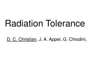
CALO radiation tolerance. The expected radiation dose in ECAL and HCAL (TDR). from CALO TDR, per 1 year at L=2∙10 32 cm -2 s -1 (2 fb -1 ) at √s=14 TeV (x20 for 4 years @ 10 33 cm -2 s -1 ). (at shower maximum). Inner equipped 32 – 96 cm. EM. Inner equipped 24 – 72 cm. hadron.

E N D
CALO radiation tolerance Yu. Guz 2012/06/15
The expected radiation dose in ECAL and HCAL (TDR) from CALO TDR, per 1 year at L=2∙1032cm-2s-1 (2 fb-1) at √s=14 TeV (x20 for 4 years @ 1033 cm-2s-1 ) (at shower maximum) Inner equipped32 – 96 cm EM Inner equipped24 – 72 cm hadron • Replaceable are: • ECAL (and HCAL) PMTs, CW bases and light guides • 48 central ECAL modules (although not an easy task) • WLS fibers of ECAL modules (check) • Not replaceable: • other ECAL modules • HCAL modules, plastic and fibers • The radiation tolerance is an issue for : • ECAL modules: scintillator and fibers • ECAL light readout elements • light guides • PMTs (entrance window) • CW boards • HCAL plastic and fibers • Not an issue for the HCAL light readout elements (lesser dose behind HCAL) Yu. Guz 2012/06/15
Passive dosimeters’ data M. Karacson, presentation at CALO meeting 2012/06/13 • The radiation levels in the CALO system are monitored by passive dosimeters placed in 4 planes, 17 dosimeters in each: • front of SPD • front of ECAL • front of HCAL • back of HCAL. • 5 dosimeters installed at modules being irradiated in the LHCb tunnel • Collected in the winter shutdown 2011/2012. Results presented by Matthias at the CALO meeting 13-Jun-2012. • Reasonable agreement with FLUKA simulation results. • The TDR predictions are compatible with these measurements, except for positions near the beam pipe at the ECAL front, where the levels are considerably underestimated in TDR (factor of ~3) Yu. Guz 2012/06/15
The radiation tolerance of ECAL modules: previous studies (TDR) • Studies performed in 1999. • scintillator tiles and fibers irradiated at LIL (LEP Injector LINAC) to doses reproducing the longitudinal dose profile at LHC • the degradation of light yield and transparency of tiles and fibers were measured after irradiation (several times; significant annealing effect observed). • degradation of light yield (N ph.el. /GeV) and energy resolution of ECAL modules obtained from simulation. a) module light yield degradation b) Energy resolution • However: • not exactly the same type of scintillator and WLS fibers as in the present ECAL; • only electromagnetic component in the irradiation; • performance obtained from simulation and not by direct measurement; • a new series of tests started c) Radiation induced constant term vs dose Yu. Guz 2012/06/15
The radiation tolerance of ECAL modules: new tests - I • A. Make use of the LHC radiation field. Two modules were placed in the LHC tunnel at the opposite side from the LHCb interaction point. • testing same type modules as in present ECAL; • same composition of the radiation field as in ECAL itself reliable estimation of rad. damage; • the dose rate is several times faster than at ECAL central modules; • modules installed in September 2010, equipped with passive and active dosimeters; • the test will last several years, with measurements with 137Cs source scanner during shutdowns • first scan performed 15-Feb-2012 • B. Perform irradiation at the PS IRRAD facility, 24 GeV protons (Maurice Glaser) • different composition of the radiation field • different dose rate and longitudinal profile – different effect on the resolution • but quick answer; and • light yield degradation measurement is robust • November 2010 – irradiated to ~2 Mrad • July 2011 – tested at the SPS electron beam • February 2012 – scan with 137Cs source • June 2012 – irradiated again, added other 2 Mrad • October 2012 – beam tests and 137Cs scan planned Yu. Guz 2012/06/15
new tests – II : irradiation at PS The dose profiles and induced activity level were calculated using FLUKA (V. Talanov). It was found that in order to obtain ~ 2 Mrad inside the module we need ~8∙1012 protons/cm2. Longitudinal dose profile, 24 GeV protons, 8∙1012/cm2 • The 10x10 cm2 central area of a Outer type (1 large cell) module’s 12x12 cm2 was uniformly irradiated, using the (x,y)-movable table. The irradiation took ~36 hours. The input proton flux was measured with Al film. It showed good dose uniformity; the input flux ~9∙1012 p/cm2 (requested 8∙1012, to have ~2 Mrad). p 24 GeV Tested in July 2011 at the SPS electron beam, along with a non irradiated module. The module performance is satisfactory, however the light yield degradation (factor of 5.5) is higher than expected from TDR results. The energy resolution roughly agree with the TDR expectations at 2 Mrad same PMT at same HV Results of the 137Cs scan 15-Feb-2012. The light yield decreased over the whole module length effects of degradation of plastic and fibers are comparable. PMT position It would be interesting to study effect of higher dose second irradiation (performed in June 2012) Yu. Guz 2012/06/15
new tests – III : irradiation in the LHC tunnel The dose measurements from the passive dosimeters in the tunnel were also presented by Matthias 13-Jun-2012 PMT position Results of the 137Cs scan 15-Feb-2012. Scanned were the cell closest to beam pipe (max dose) and the one at the opposite side (min dose). For comparison, scan before irradiation (2009) is shown. These tests done with different PMTs at different HV, so only shapes can be compared. No visible degradation, at the first glance. Tests with electron beam can be more sensitive. Yu. Guz 2012/06/15
The radiation tolerance of ECAL light readout elements PMT entrance window transparency degradation and CW board radiation tolerance were tested in April 2010 at the 50 GeV proton beam at IHEP Protvino. The light guides are still to be tested (cheap and easily replaceable no problem expected). The CW boards remain operational till more than 1.5 Mrad (!) (~25 fb-1). Total of several hundred CW boards should be replaced during LHCb operation after upgrade. This can be done in winter shutdowns. not irradiated 2 Mrad Another issue, not related to the radiation, is the PMT dynode system ageing (wearing) while working at high anode currents. We see the effect already now, most pronounced in HCAL. The PMT gain therefore should be kept low, additional amplification applied in frontend electronics. PMT entrance window degradation at 2 Mrad (~32 fb-1) is ~5% at 476 nm (Y11 emission peak) - not going to be a problem. not irradiated irradiated 2 Mrad Yu. Guz 2012/06/15
Spares • Available are 33 spare ECAL Inner type modules one replacement of the innermost modules. For more replacements, additional production of modules should be foreseen (if feasible at all). • Alternatively, one can (meeting 27-Mar-2012) • try to replace only WLS fibers in situ, for at least partial recovery • and/or try to force recovery of plastic transparency during shutdowns with UV, heating, etc • ~500 spare HAMAMATSU R7899-20 PMTs exist, to replace “aged” ones; • it is (almost) straightforward to produce necessary amount, ~1000, of spare ECAL CW boards. Yu. Guz 2012/06/15
beam spacers scintillators WLS fibers lightguide master plate PMT Radiation damage of HCAL The HCAL radiation tolerance was not studied before. Anyway, the modules are not replaceable. HCAL cells are longer in Z than ECAL longer WLS fibers faster degradation expected. However, its performance is much less crucial. Longitudinal dose in HCAL, cell closest to the beam row 0 row 1 row 2 row 3 0 1 2 3 4 5 HCAL tile row row 4 row 5 The hadronic shower maximum lays within the tile row 0 (ECAL is ~1.2 λI); the dose in the row 5 is much less. No significant radiation damage to the LED system, PMTs, their Cockcroft-Walton boards, and integrators of the source calibration system, as all that is placed behind row #5. Yu. Guz 2012/06/15
Radiation damage of HCAL light yield As at 137Cs calibration response of every individual tile is measured, the radiation damage of the HCAL light yield of scintillator tiles and fibers in a tile row #i can be determined as a decrease of relative response of this row, (Ai/A5), with respect to a reference 137Cs run at lumi=0: The dependence of central average on delivered luminosity in 2011 is shown. After 1 fb-1, it is ~8% in the row #0; less for the row #1 etc. In 2011 it developed ~ linearly in time. The figure is to be updated with the next scan data (25-Jun). Yu. Guz 2012/06/15