Download
1 / 18
180 likes | 246 Vues
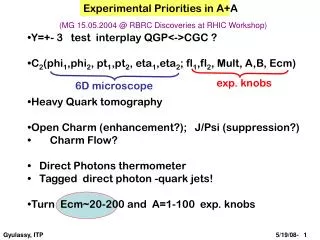
Status of cogging December 4, 2013 Creig Drennan , Bill Pellico , Kiyomi Seiya , Kent Triplett, Alex Waller. LLRF Room. G16-RR2-1. G14-RR5-1. G11-RR7-1. Cables to 48 correctors from LLRF room (K. Triplett, D. Dick). A OUT 1. A OUT 1. A OUT 2. A OUT 2. A OUT 3.

E N D
Status of coggingDecember 4, 2013CreigDrennan, Bill Pellico, KiyomiSeiya, Kent Triplett, Alex Waller
LLRF Room G16-RR2-1 G14-RR5-1 G11-RR7-1 Cables to 48 correctors from LLRF room (K. Triplett, D. Dick) A OUT 1 A OUT 1 A OUT 2 A OUT 2 A OUT 3 A OUT 3 B OUT 1 B OUT 1 B OUT 2 B OUT 2 B OUT 3 B OUT 3 +A IN +A IN +B IN +B IN 5 5 5 5 5 5 1 1 1 1 1 1 2 2 2 2 2 2 6 6 6 6 6 6 8 8 8 8 8 8 3 3 3 3 3 3 4 4 4 4 4 4 7 7 7 7 7 7 East Gallery BLLRF-4 Module PP-D BACK PP-2 BACK PP-2 BACK PP-2 A OUT 3 B OUT 3 A OUT1 B OUT 1 A OUT 2 B OUT 2 A IN 8 A OUT1 7 A OUT2 H(S,L) 16 ~ 19 V(S,L) 16 ~ 19 H(S,L) 12 ~ 15 V(S,L) 12 ~ 15 H(S,L) 08 ~ 11 V(S,L) 08 ~ 11 A OUT 3 A OUT 2 B OUT 1 A OUT 1 B OUT 2 B OUT 3 6 B IN 5 H(S,L) 20 ~ 23 V(S,L) 20 ~ 23 H(S,L) 24 ~ 03 V(S,L) 24 ~ 03 H(S,L) 04 ~ 07 V(S,L) 04 ~ 07 B OUT1 4 B OUT2 FRONT PP BACK PP-2 BACK PP-2 BACK PP-2 16 15 14 13 West Gallery G21-RR4 G21-RR4-2 G24-RR4-1 G04-RR0-6
Test stand at LLRF room (K. Triplett, T. Boes)
MFC board (AD/LLRF) TCLK decoder on FPAG (AD/Control) ADC FPGA DSP DAC
MFC board I/O (1) (C. Drennan) DIGITAL INPUT TCLK Bdot Booster RF pulse MI RF pulse OAA DIGITAL OUTPUT Trigger to nocher DAC OUTPUT Offset to corrector RPOS RF To pulse Digital I/O To Harting connector (LVDS) 4 channel outputs with 0-700mV Buffer amp gain offset
MFC board I/O (2) Digital input To Harting connector RF To pulse
New Booster LLRF board (C. Drennan)
Booster cycle 1st pulse 2nd pulse Intensity B field Notch @ 400msec @ 7msec The notch was created at 7msec for the 2-12th pulse. Creating the notch at lower energy can reduce beam loss in the Booster.
Total bucket counts during Booster cycle The bending field in the Booster, injection energy, timing, rf feedback …..are changing from pulse to pulse and bucket position at extraction is not constant.
Difference of bucket count between reference cycle and a cycle with B field error. Final bucket position
DAC output on $19 Turn Number
Beam study on $17 $12 $17 $17 $17 $17 57 bucket /div
Magnetic cogging B+dB Fixed with RPOS feedback Changed by dipole corrector Dipole corrector: 0.009[T-m] @ 24.4[A] (Assuming 10[A] change ) B field error ~1% can be compensated. Keeps the orbit centered and saves aperture. Has two feedback loops for frequency and RPOS .
Beam study on $17(1) w/o dipole corrector with
Beam study on $17(2) Orbit difference Corrector current
Data on JAVA application (A. Waller) 4 array data from memory
Dbuckets compensation with RPOS cogging and Magnetic cogging
Plans Beam studies on $17 and optimize gain. Combine MCOG( before transition) and RCOG (after) on MFC board. Creating the notch at 1msec.