Download

1 / 21
630 likes | 2.25k Vues
Wire Bonding Quality Issues. Outline. Very brief intro to wire bonding QA for wire bonding Quality issues from the bonding service Q issues from module design and construction Conclusions. A. Honma and I. McGill, CERN PH/DT. Brief Intro to Wire Bonding. Some terminology:.

E N D
Wire Bonding Quality Issues Outline • Very brief intro to wire bonding • QA for wire bonding • Quality issues from the bonding service • Q issues from module design and construction • Conclusions A. Honma and I. McGill, CERN PH/DT Workshop on Quality Issues in Current and Future Silicon Detectors
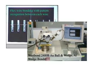
Brief Intro to Wire Bonding Some terminology: 2003 Bond Workshop at CERN: http://ssd-rd.web.cern.ch/ssd-rd/bond/default.htm CERN Bondlab: http://bondlab-qa.web.cern.ch/bondlab-qa/Bondlab_Home.html Our bonding tips: http://bondlab-qa.web.cern.ch/bondlab-qa/Recommendations.html An excellent web resource (bonding and packaging): http://extra.ivf.se/ngl/ The “Bible”: Harman, G., Wire Bonding In Microelectronics, McGraw-Hill, 2010 ISBN 0071476237 chip/sensor loop 1st (source) bond foot substrate (PCB, ceramic, silicon) 2nd (destination) bond foot heel bond pad Some bonding reference links: Workshop on Quality Issues in Current and Future Silicon Detectors
Brief Intro to Wire Bonding Wire bonding performed for HEP: why aluminium wedge over gold ball ? Aluminium wedge ultrasonic Gold ball thermosonic (industry standard) Room temperature process More control (larger parameter window) Better at fine pitch Excellent reliability on Al bond pads Good reliability on PCB/Kapton bond pads Used almost exclusively for unpackaged HEP wire bonding applications Needs heating of substrate (>150°C) Smaller parameter window Almost as good at fine pitch Good reliability on Al bond pads Problematic on PCB/Kapton Faster Used in ~90% of industrial packaged chips but copper wire use increasing Workshop on Quality Issues in Current and Future Silicon Detectors
Quality Assurance for Wire Bonds What QA is normally applied for wire bonding? • visual inspection • pull test (destructive or NDT) – DT for production • if subject to thermal changes, thermal cycling followed by pull test recommended • if subject to vibration damage: vibration studies • if high reliability needed: accelerated aging tests, humidity/temp tests Want high mean strength, low RMS and no “lifts” Although much of what is wire bonded in silicon detectors has redundancy, the fact that it must continue to function for 10-20 years with no repair requires high reliability. Workshop on Quality Issues in Current and Future Silicon Detectors
Quality Issues in HEP silicon detectors Bonding Service Issues: machine problems: many possible but usually easy to identify => pre-calibrated test pieces damaged or dirty tool: causes (hard to notice) weak or damaged bond foot wire problems: rare but can be difficult to identify (twist, kinks, "bad wire”) ESD damage to wires or via wires to chip or sensor (rarely caused by bonding machine) handling damage to wires cleanliness of bonding surfaces (clean room!) poor wire loop choice (chip corner clearance, high loop heel weakening) “Module” design and construction issues: • non-optimal bond pad design (dimensions, placement, #rows, passivation window) • incorrect choice of bond pad metallization on substrates (chip, PA, PCB) • incorrect manufacturing of bonding metallization (wrong or contaminated metal, wrong thicknesses, adhesion failure, passivation, smoothness, planarity, flatness, ...) • contamination/particulates on bond pad surfaces • damage to bond pads (probing) • halogen induced corrosion (particular to aluminium) • poor alignment or planarity of substrates • poor support of substrates (jigs) • loop constraints (height difference, clearance, foot-foot distance, etc) • ESD damage to wires or via wires to chip or sensor • handling damage to wires • pros and cons of protection of wires (encapsulation) • wire melt from over-current • breakage from vibration of support structures during handling and transport • breakage from vibration in magnetic fields • Insufficient clearance for bond tool and head (machine dependent) Many other issues are not mentioned here, these are just a selection of those we see most often or are known to have been important during LHC construction. Workshop on Quality Issues in Current and Future Silicon Detectors
Examples: Main Bonding Service Quality Issues Machine problems: Over-deformation – too much power, force, or time. Can be the result of poor surface quality. Post-bonding visual inspection is important! marginal rejected acceptable can severely weaken the heel 50μm Machine problems:Cratering of silicon – again, too much power, force, or time. Can occur and not be seen unless complete fracture occurs with lift of bond foot. Worst cases detected in pull-tests. Usually “OK” on chips but not on sensors. SEM photo of a cratered pad: Normal bond pad with foot removed Crater in silicon Metallization removed exposing silicon surface Workshop on Quality Issues in Current and Future Silicon Detectors
Examples: Main Bonding Service Quality Issues Poor bond loop choice: Bond loop parameters leading to chip edge touching. The solution is simple but seeing the problem may be less obvious. May lead to short circuit if edge of chip is metallized or at a large potential difference. In the case of a read-out wire at the edge of a biased p-on-n sensor, the edge is at high voltage and a minimum clearance is required (typically 100 μm) to avoid corona discharge. Wire touches edge of chip All the “bond lab” problems shown so far occurred during the CMS tracker hybrid production bonding done in industry, but were detected in the reception visual inspection and bond tests at CERN. It indicates the need for continued quality control after initial qualification. Workshop on Quality Issues in Current and Future Silicon Detectors
Examples: Module Design + Construction Bonding Issues Non-optimal bond pad design: Aluminium wedge wire bonding with standard 25um wire requires a rectangular pad of at least 60μm x 150μm for best results. Even wider pad needed if skew bonding will be required. Examples of skew bonding problems on undersized or poorly designed pads High risk of shorting adjacent pads, extremely accurate bond placement required. Reduced contact area and weakened heel (wire pushed over edge of pad by bond tool), risk of heel crack. Workshop on Quality Issues in Current and Future Silicon Detectors
Examples: Module Design + Construction Bonding Issues Contamination/corrosion: Bond pad and wire damage from foreign substances on surfaces. Can migrate long distances over surface with humidity or voltage. Worst case for aluminium wires is presence of chlorine and water, can totally convert Al to Al(OH)3 which is a white powder. Solution: proper cleaning and verification. Wires in air, totally eaten through. chlorine Picture credits: http://www-rhvd.fnal.gov/chips/Pict_and_Plots/DamagedPreFPIX2pcb/pcbdamage.htm Although this example is from FNAL, we have seen this phenomenon in at least 4 CERN related silicon projects, including CMS and ATLAS. Workshop on Quality Issues in Current and Future Silicon Detectors
Examples: Module Design + Construction Bonding Issues Improper metallization on Si, ceramic or glass: Metal layer adhesion failure, usually aluminum on silicon or glass (pitch adapter). Like cratering, but not the fault of the bonding machine. Metal layer lifts off of substrate with bond foot during bonding or sometime later.Solution: solve adhesion problem with manufacturer (test pieces). Al on silicon adhesion failure during bonding Pitch adapter pull test adhesion failure of 2nd Al layer (1st layer was probably overly oxidized). Workshop on Quality Issues in Current and Future Silicon Detectors
Examples: Module Design + Construction Bonding Issues Improper metallization on PCB #1: Bond pads too narrow owing to over-etching, surface not flat, “bumpy”, or like “Swiss cheese”. Insufficient surface area of weld under bond foot leading to lifts during bonding or poor bond strength. Solution: Put into specifications and reject non-conformity (or find a better company). Over-etching Difficult rounded surface Good flat surface 30 μm ! (made in Germany) (made in Italy) Bond foot was here normal surface aspect “Swiss cheese” surface aspect Workshop on Quality Issues in Current and Future Silicon Detectors
Examples: Module Design + Construction Bonding Issues Improper metallization on PCB #2: “Black pad”, “purple plague”, metal migration, intermetallic voids, oxidation, etc. Believed to be from incorrect thicknesses, contamination of baths, poor choice of metals or process, … Solutions: Thickness measurements, cross-sections, chemical analyses, spectroscopic analyses, bond pull testing, imposing high IPC standards may be required to avoid these problems, often occurring in the manufacturing process. Some require accelerated aging tests or current/voltage stress tests. black pad metal migration Metal migration is when metals diffuse through other metals, either thermally or electrically driven. Here Cu moved through the Ni and Au. Black pad is severe oxidation of the nickel layer in Cu-Ni-Au PCB metallization. No weld is possible. Workshop on Quality Issues in Current and Future Silicon Detectors
Examples: Module Design + Construction Bonding Issues Poor support of substrates: A good jig design should support the substrates to be bonded so that they do not move during bonding. Sometimes the module design itself precludes proper support. This can lead to substrate bounce which can severely weaken or break wires. Wire bonds Read-out chip Silicon sensor glue PCB hybrid Carbon fibre support frame Vacuum support pads Variation in material thicknesses and non flatness may lead to gaps and substrate bounce If bonding on this end, may get flexing because of distance from support point Bonding Jig Solutions are not always easy because of difficulty of access and inability to control thickness variations and flatness. Sometimes ad hoc solutions (shims, clips, even tape) are necessary to get good support as close as possible to the areas underneath the bond feet. Any movement (sideways and vertical) of the substrate during bonding can result in failed or poor bond quality. Workshop on Quality Issues in Current and Future Silicon Detectors
Examples: Module Design + Construction Bonding Issues • Damage to bond pads: More of an issue for gold ball bonding but probe damage can also degrade aluminium wedge wire bonding as well. Need enough Al on pad to make the weld! Scratched through to the silicon in the uniform dark grey areas in center of the probe marks. Nice small probe mark, should have been at the end of pad but plenty of space for bond foot. • Solution: make the area for probing away from bonding or take great care using very small probe tip with a light contact . Workshop on Quality Issues in Current and Future Silicon Detectors
Examples: Module Design + Construction Bonding Issues Broken or damaged wires: Usually coming from handling or transport. What passes through our lab is clearly mostly handling damage. Very easy to damage bond wires without even realizing it (fingers, clothes, tools). Most of the time: beautifully uniform set of 128 wires into a CMS tracker APV readout chip. Difficult installation access and clearances, module handling points close to bond wires and “operator error” resulted in almost 400 CMS tracker endcap modules coming to the CERN bond lab for wire damage repair, mostly minor. This one, however, was deemed “beyond repair”… Solution: better installation tooling, better training of personnel, encapsulation, … SEM pic of wire heel crack from resonance in mag field? Workshop on Quality Issues in Current and Future Silicon Detectors
Examples: Module Design + Construction Bonding Issues Broken or damaged wires: Transport was found to be responsible for early module bond wire damage. The culprit was large differential motion of components driven at a resonant frequency. Vibration tester found resonant oscillation mode on a silicon module at 69 Hz. Typical transport frequency spectrum goes from 0 – 2 KHz. SEM photo courtesy CERN EN/MME-MM Wires that are made to oscillate because the two feet move with respect to each other tend to break at the first bond heel. Metal fatigue causes heel crack. CMS Solution: encapsulation with a silicone polymer or reinforcement of substrates. Workshop on Quality Issues in Current and Future Silicon Detectors
Examples: Module Design + Construction Bonding Issues Broken or damaged wire protection by encapsulation Clear silicone encapsulant, two component room temperature cure, very fluid before curing. Need to test: Encapsulant does not damage or break wires upon curing Wires and encapsulant can survive thermal cycling of real environment Can survive radiation Proper filling of volume (no large voids) Can see bond wires, an air bubble and a needle stuck in the encapsulant. Note: one loses reworkability Workshop on Quality Issues in Current and Future Silicon Detectors
Examples: Module Design + Construction Bonding Issues Other issues and advice: Think about bonding related problems in chip, sensor, fan-out and module at the design stage Be aware of bond wire metal to substrate metal combinations in terms of intermetallic compound formation (reliability issue): (best) Al – Al, Al – Ni, Al – Pd, Al – Au, Al – Cu, Al – Ag (worst) Provide adequate mechanical and ESD protection for bond wires during transport and handling. Use vibration testing for damage prevention. Avoid allowing movements of substrates such as during thermal cycling which may cause wires to flex. If critical wire bonding is to be done in industry, need tough specs, full qualification, and thorough testing (by you or other external expert). Cleanliness of surfaces (particulates, residues can degrade bond quality) Share information on wire bonding problems Don’t use wire bonding where a connector or soldering could be used Redundancy is always good, add extra bond wires for critical connections Only one needed but 7 wires bonded Workshop on Quality Issues in Current and Future Silicon Detectors
Conclusions • Wire bonding (Al, Au, and Cu) will continue to be needed for the foreseeable future of silicon detectors. • QA procedures and reliability testing techniques exist to assure a good quality result. • The majority of wire bonding problems we encounter are not problems with the bonding machine or process but rather of the dimensions and metallization of the bond pads. Good bond pad design and especially PCB process control is essential. • The LHC silicon detectors production wire bonding went relatively smoothly, although there are clearly areas for significant improvement. The next generation detectors will still require large number of wire bonds so attention to wire bonding related QA is recommended. • Please feel free to contact Ian McGill or myself for bonding related questions or advice. Workshop on Quality Issues in Current and Future Silicon Detectors
Extra slides Workshop on Quality Issues in Current and Future Silicon Detectors
Examples: Module Design + Construction Bonding Issues Non-optimal bond pad design: Too short pad dimensions and thick passivation window can lead to weakened or broken heels. This lead to 2g pull test failures in CMS tracker hybrids. Solution: care in foot placement and frequent pull testing. Better: proper pad dimensions for Al wedge. APV read-out chip, control bonds. Put 2 wires per signal for redundancy but pad should have been one large one not 2 small square ones. Reduced contact area and weakened heel (wire pushed over edge of pad) Wires removed to show damage to passivation implying likelihood of damage to bond heel Al bond pad corner Passivation 5-7 μm silicon Workshop on Quality Issues in Current and Future Silicon Detectors