Download
1 / 28
280 likes | 395 Vues
Implementation, Comparison and Literature Review of Spatio-temporal and Compressed domains Object detection. By Gokul Krishna Srinivasan Submitted to Dr K.R.Rao. Implementation, Comparison and Literature Review of Spatio-temporal and Compressed domains Object detection. By

E N D
Implementation, Comparison and Literature Review of Spatio-temporal and Compressed domains Object detection. By Gokul Krishna Srinivasan Submitted to Dr K.R.Rao Implementation, Comparison and Literature Review of Spatio-temporal and Compressed domains Object detection. By Gokul Krishna Srinivasan Submitted to Dr K.R.Rao
Objective • Object detection in a moving video stream is playing a prominent role in every branch of science and research [1]. • Objection detection or tracking is done by two different methods • Spatio-temporal domain • Compression domain • This project will deal with both the domains in order to bring out the advantages and disadvantages of each and every method in terms of complexity in computations and efficiency.
Compressed Domain • Exploits the encoded information like motion vectors, discrete cosine transform (DCT) [1] coefficients, and macroblock types which are generated as a compressed bit stream [1, 2, 3 & 6] • Uses motion vectors or DCT coefficients as resources in order to perform object detection and tracking [6]. • The five different blocks are reference block Br, current block Bc, background block Bb, moving block Bm and unmoving block Bu • The algorithm consists of four different steps initial region extraction, moving region detection, unmoving region creation and updating and modification of vector featured regions [2].
Figure 1 shows the initial region extracted from the motion vector values, in fig 2 the label fn-2, fn-1, and fn represent the corresponding frame and each block in the frame represents a macro block motion vector value. The initial regions are formed by one to one mapping of the previous and the next corresponding frame. Fig.1: Each block in the figure represents a macro block motion vector value, [2].
Motion vector calculation: • Using the previous and the future frame as reference, the encoder finds the motion vectors for the forward and backward prediction frame • Each video sequence is divided into one or more group of pictures • The encoder outputs the motion vectors in the bit stream order • Only the motion vectors that are received in the decoder side are processed to find the moving object region. Fig 3: MPEG group of pictures – Display order [6].
Frames do not come into the decoder in the same order as they are displayed. The ouput frames from the encoder will be of the form I P B B P B B I B B P B B. Where I is the intra coded frame, P is the predicted frame and B is the bi-directionally predicted frame. • First, reorder the incoming frames or slice from bit stream order to display order. • To reorder the frames to the display order the following procedure is followed • If an I or P frame comes in put it in a temporary storage called future. • I or P is left in the future until another I or P frame comes in, on the arrival of a new I or P frame, already present I or P frame is taken out from the temporary storage called future and is put in the display order and the newly arrived I or P is put into the temporary storage called future. • All B frames are immediately put in the display order. • At the end whatever frame is left in the temporary variable called future is put in the display order.
Fig 4: Conversion from bit stream order to display order [6].
Algorithm for storing the motion vectors in respective arrays: • The motion vectors are stored in a two dimensional arrays and the size of the array corresponds to the frame size in macro block (in this case 8x8 macro block was chosen). • The forward prediction vectors and backward prediction vectors are stored in separate arrays. • Each prediction vector in turn contains two more arrays to store the horizontal and vertical movement of vectors. • To find the motion from one frame to another, a record of motion vectors of the previous frame has to be kept. • Fig 5 shows the explanation of the algorithm in a flow chart. • The process of inputting the motion vectors into correct arrays and reordering the frames into the display order were incorporated in the decoder. • The final output of this algorithm stores the motion vectors of successive frames in an array.
Fig 5: Flow chart explaining storage of motion vectors in respective arrays. [6].
For finding the motion from frame to frame, the present and previous frame motion vectors are subtracted. • If an ‘I’ frame is encountered all the values in the array are set to zero. • If a B frame is encountered, forward prediction and backward prediction vectors are subtracted separately and an average total motion is found in both the horizontal and vertical directions. • The obtained motion vectors for each frame are written into a separate file each for horizontal and vertical motions.
Moving Region Detection: • A moving object generates non-zero motion vectors that appear continuously over multiple frames. • The continuous appearances of motion vectors cause previous block and current block motion vectors to overlap, these regions are detected as moving regions Bm. • When a current frame pointed to is an I-frame, then no motion vectors information will be there In the current frame and hence the contents of motion vector information from previous vector-featured image is copied to present frame, moving block is not created in these frames.
Unmoving region creation and updating: • A block which was having a motion vector in the previous frame may tend to a zero motion vector in the current frame. • These regions are marked as unmoving regions as the moving object is expected to exist after current frame. • When a moving object stops, zero motion vectors are generated, however just before the object stops, moving block regions will be created along the movement of the object whose current block has a zero motion vector. • These regions whose previous motion vector value had a moving block related to the current zero motion vector is marked as unmoving block. • The effect of the unmoving block is also crucial, there are two criterions that should be considered, one is that the unmoving regions should be considered correctly and a object which has moved in position after few frames should also be noted. • For these issue unmoving block regions are monitored for some k frames, if a zero motion vector persists its brightness value is decreased gradually, if not it is marked as a moving block region.
GUI for annotating object locations: • The obtained results of moving object detectionfrom both the methods are compared with the manually annotated hand location gives the coordinate location of the centre of the object in every frame. • The user selects a video filename from the list of filenames present in the drop down box, the second edit box holds the start frame number and the third edit box holds the end frame number as entered by the user. • On clicking the get frame button, a separate window opens which contains the image of the particular frame number that lies between the start and end frame. • Using a marker tool the user annotates the hand location by which the coordinate locations are obtained. • The hand locations obtained between the start and the end frame are stored in an array which forms the bench mark for evaluating the accuracy of moving object detection. • Fig 6 shows the GUI that has been created for manually annotating hand locations.
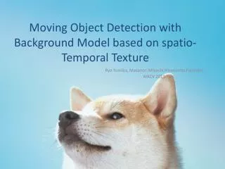
Spatio-Temporal Object Detection: • Identifies moving objects from portion of a video frame that differs significantly from a background model • There are four main steps in a background subtraction algorithm [5], they are preprocessing, background modeling, foreground detection and data validation as shown in fig.7. Figure 7 : Steps in background subtraction algorithm
Non-recursive technique uses a sliding window method and it stores a buffer of the previous L video frames, and estimates the background image based on the temporal variation of each pixel within the buffer [5, 7]. • Recursive technique is a non-adaptive technique and does not use past input frame information. Foreground detection just compares the input frame with the background model and uses a threshold value as in binary classification [5, 7]. • Data validation is the process of improving the candidate foreground mask based on information obtained from outside the background model. • All the background models have three main limitations, first, they ignore any correlation between neighboring pixels; second, the rate of adaption may not match the moving speed of the foreground objects; and third, non-stationary pixels from moving objects are easily mistaken as true foreground objects. • These limitations of background model are reduced in foreground detection and the possibility of false detection is also reduced.
Parametric and non-parametric object detection: Steps to be performed for the parametric model of object detection: Estimate the mean and standard deviation of a particular color object to be detected from the sub window block which contains only particular color pixel values. Find, P1 (RGB/color), which forms the training set, Assume that colors are mutually independent, then, P1 (RGB/color)=P1 (R/color)*P1 (G/color)*P1 (B/color) Each P1 (R/skin), P1 (G/skin) and P1 (B/skin) are estimated through Gaussian probabilities. Gaussian PDF is given as, F(x) = where, F(x) Functional Gaussian probability estimate of data x. x The sample data whose Gaussian probability has to be found. mThe mean value of the object to be detected. Sigma Standard deviation. Maximum likelihood estimate is then applied to the obtained Gaussian probability model to obtain the color object region from the video frame [5 & 7].
A non-parametric model of object detection uses minimum or no parametric estimate to perform object detection. • An example of non-parametric model is histogram based object detection • For example, to detect green object, the each color image pixel is made up of overlapping red, green and blue intensity values, cancel out the green pixel intensity with that of the red pixel and also with the blue pixel intensity values, the formulation becomes [7] • F(i,j)=2*Ig(i,j,2)-Ir(i,j,1)-Ib(i,j,3), where 1≤i≤N , 1≤j≤M • N and M are row and column lengths of the image I(N,M). • Ig(i,j,2) is the index of the green pixel intensity and similarly for • Ib(I,j,3) is the index of the blue pixel intensity • Ir(I,j,1) is the index of the red pixel intensity • F(i,j) is the final functional value of the green color density distribution.
Experimental results - spatio-temporal moving object detection: • Localized output box count precision: • This metric count the number of output boxes that significantly covered the correctly classified object obtained from training • An output box D in each frame significantly covers the ground truth if a minimum proportion of its area overlaps with detection box G • Ground truth can be defined as the area under the actual moving object in each frame or can also be defined as a correct classification in each frameLoc_box_count = box_prec(D) = Where, Ug is the union space of total number of pixels in the detection box. |D | is the pixel count of output detection box overlapping with the ground truth. Overlap min is the minimum proportion of the output box’s area that should be overlapped with the ground truth in order to say that output is precise.
Average detected box area precision: • This metric provides the average of detection boxes precision in covering the area that ground truth object covers in each frame. • Precision = • Box precision (D) = Where,D= output detection boxes in each frame; Ug=Spatial union of ground truth detection
Figure 8: Hand movement detected for frame #100, 5 detection boxes of size 150X150 Figure 9: Hand movement detected for frame #115, 5 detection boxes of size 150X150
Experimental results - moving object detection using motion vectors • The motion vector values that are obtained were result of an 8x8 macro block encoding, the frame size used in this project is 240x320, and hence the motion vector values obtained for each frame were of size 30x40 • In order to represent the moving object detection using motion vectors, the direction vector plot of each frame is plotted as shown in fig 10. • The constraints that to be considered in compressed domain object detection using motion vector estimate is that, if the test video has moving background objects other than object to be detected then the accuracy of detection will be less. • Using connected component analysis and setting up a threshold value, the regions of maximum displacement is obtained, in this frame the maximum motion vector after setting the threshold is found to be at array index [33,15] which is [264, 120] pixel location in the original spatial frame coordinate location • The threshold value must be selected such a way that the important information from the motion vector should not be erased
Figure 10: Motion vector values from frame #42 of close detect 1. Figure 11: Threshold motion vector values for frame #115
Table 1: Percentage of correct detection Fig 12: Accuracy of detection
Conclusions: • The performance of moving object detection is evaluated using two different techniques • The experimental results show that the accuracy of moving object detection in spatio-temporal domain is better than that of the compressed domain motion vector based moving object detection.
Reference Qiya Z and Zhicheng L, “Moving object detection algorithm for H.264/AVC compressed video stream”, ISECS International Colloquium on Computing Communication, control and management, vol. 1, pp. 186-189, Sep, 2009. Yokoyama T, Iwasaki T, and Watanabe T,” Motion vector based moving object detection and tracking in the MPEG Compressed Domain”, Seventh International Workshop on content based Multimedia Indexing, pp. 201-206, Digital Object Identifier: 10.1109/CBMI.2009.33, Aug, 2009 Kapotas K and Skodras A. N,” Moving object detection in the H.264 compressed domain”, International Conference on Imaging systems and techniques, pp. 325-328, , Digital Object Identifier: 10.1109/IST.2010.5548496, Aug, 2010 Sen-Ching S. C and Kamath C,” Robust techniques for background subtraction in urban traffic video” Center for Applied Scientific Computing, Lawrence Livermore National Laboratory, vol. 1, pp. 586-589, Jul 2004.
Elhabian S. Y, El-Sayed K. M,” Moving object detection in spatial domain using background removal techniques- state of the art”, Recent patents on computer science, Vol. 1, pp. 32-54, Apr, 2008. Sukmarg O and Rao K. R,” Fast object detection and segmentation in MPEG compressed domain”, TENCON 2000, proceedings, vol. 3, pp. 364-368, Mar, 2000. Thompson W. B and Ting-Chuen P,” Detecting moving objects”, International journal of computer vision, vol. 6, pp. 39-57, Jun, 1990. JM software - http://iphome.hhi.de/suehring/tml/ Mariano V. Y., et al,” Performance evaluation of object detection algorithms” International conference on pattern recognition, Vol.3, pp. 965 – 969, June 2002.