Download
1 / 36
360 likes | 365 Vues
CS 378 Programming for Performance Single-Thread Performance: Review of Pipelining. Siddhartha Chatterjee Spring 2008. A. B. C. D. Pipelining: It’s Natural!. Laundry Example Ann, Brian, Cathy, Dave each have one load of clothes to wash, dry, and fold Washer takes 30 minutes

E N D
CS 378Programming for PerformanceSingle-Thread Performance: Review of Pipelining Siddhartha Chatterjee Spring 2008
A B C D Pipelining: It’s Natural! • Laundry Example • Ann, Brian, Cathy, Dave each have one load of clothes to wash, dry, and fold • Washer takes 30 minutes • Dryer takes 40 minutes • “Folder” takes 20 minutes Siddhartha Chatterjee
Sequential laundry takes 6 hours for 4 loads If they learned pipelining, how long would laundry take? 6 PM Midnight 7 8 9 11 10 Time 30 40 20 30 40 20 30 40 20 30 40 20 T a s k O r d e r A B C D Sequential Laundry Siddhartha Chatterjee
Pipelined laundry takes 3.5 hours for 4 loads 6 PM Midnight 7 8 9 11 10 Time 30 40 40 40 40 20 T a s k O r d e r A B C D Pipelined Laundry: Start work ASAP Siddhartha Chatterjee
6 PM 7 8 9 Time 30 40 40 40 40 20 T a s k O r d e r A B C D Pipelining Lessons • Pipelining doesn’t help latency of single task, it helps throughput of entire workload • Pipeline rate limited by slowest pipeline stage • Multiple tasks operating simultaneously • Potential speedup = Number pipe stages • Unbalanced lengths of pipe stages reduces speedup • Time to “fill” pipeline and time to “drain” it reduces speedup Siddhartha Chatterjee
Cycle 1 Cycle 2 Cycle 3 Cycle 4 Cycle 5 Ifetch Reg/Dec Exec Mem WrB Load The Five Stages of Load • Ifetch: Instruction Fetch • Fetch the instruction from the Instruction Memory • Reg/Dec: Registers Fetch and Instruction Decode • Exec: Calculate the memory address • Mem: Read the data from the Data Memory • WrB: Write the data back to the register file Siddhartha Chatterjee
Ifetch Reg/Dec Exec Mem WrB Load Key Ideas Behind Instruction Pipelining • The load instruction has 5 stages: • Five independent functional units to work on each stage • Each functional unit is used only once! • A second load can start doing Ifetch as soon as the first load finishes its Ifetch stage • Each load still takes five cycles to complete • The latency of a single load is still 5 cycles • The throughput is much higher • CPI approaches 1 • Cycle time is ~1/5th the cycle time of the single-cycle implementation • Instructions start executing before previous instructions complete execution CPI Cycle time Siddhartha Chatterjee
Cycle 1 Cycle 2 Cycle 3 Cycle 4 Cycle 5 Cycle 6 Cycle 7 Clock 1st lw Ifetch Reg/Dec Exec Mem WrB 2nd lw Ifetch Reg/Dec Exec Mem WrB 3rd lw Ifetch Reg/Dec Exec Mem WrB Pipelining the Load Instruction • The five independent pipeline stages are: • Read next instruction: The Ifetch stage • Decode instruction and fetch register values: The Reg/Dec stage • Execute the operation: The Exec stage • Access data memory: The Mem stage • Write data to destination register: The WrB stage • One instruction enters the pipeline every cycle • One instruction comes out of the pipeline (completed) every cycle • The “effective” CPI is 7/3 (tends to 1); ~1/5 cycle time Siddhartha Chatterjee
Cycle 1 Cycle 2 Cycle 3 Cycle 4 Cycle 5 Cycle 6 Cycle 7 Cycle 8 Clock Ifetch Reg/Dec Exec Mem WrB 0: Load 4: R-type Ifetch Reg/Dec Exec Mem WrB 8: Store Ifetch Reg/Dec Exec Mem WrB 12: Beq (target is 1000) Ifetch Reg/Dec Exec Mem WrB End of Cycle 7 End of Cycle 4 End of Cycle 5 End of Cycle 6 A More Extensive Pipelining Example • End of Cycle 4: Load’s Mem, R-type’s Exec, Store’s Reg, Beq’s Ifetch • End of Cycle 5: Load’s WrB, R-type’s Mem, Store’s Exec, Beq’s Reg • End of Cycle 6: R-type’s WrB, Store’s Mem, Beq’s Exec • End of Cycle 7: Store’s WrB, Beq’s Mem Siddhartha Chatterjee
Cycle 1 Cycle 2 Clk Single Cycle Implementation: Load Store Waste Cycle 1 Cycle 2 Cycle 3 Cycle 4 Cycle 5 Cycle 6 Cycle 7 Cycle 8 Cycle 9 Cycle 10 Clk Multiple Cycle Implementation: Load Store R-type Ifetch Reg Exec Mem Wr Ifetch Reg Exec Mem Ifetch Pipelined Implementation: Load Ifetch Reg Exec Mem Wr Store Ifetch Reg Exec Mem Wr R-type Ifetch Reg Exec Mem Wr Single Cycle vs. Multiple Cycle vs. Pipelined Siddhartha Chatterjee
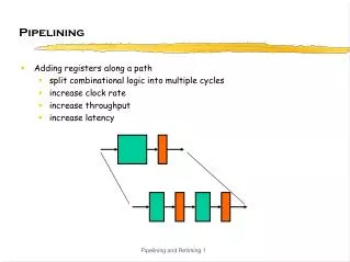
Basics of Pipelining • Time • Discrete time steps • Represented as 1, 2, 3, … • Space • Pipe stages or segments (things that do processing) • Represented as P, Q, R, S (or F, D, X, M, W for the DLX pipeline) • Operands • Instructions or data items • Things that flow through, and are processed by, the pipeline • Represented as a, b, c, … • In drawing pipelines, we conceal the obvious fact that each operand undergoes some changes in each pipe stage Siddhartha Chatterjee
Notations for Describing Pipelines • Space-time diagram, • or Gantt chart • Reservation table by stages • Rows represent pipeline • stages • Unbounded one way • Notation of HP • Reservation table by • instructions • Rows represent operands • Unbounded both ways Siddhartha Chatterjee
Basic Terms • Filling a pipeline • Flushing or draining a pipeline • Stage or segment delay • Each stage may have a different stage delay • Beat time (= max stage delay) • Number of stages • End-to-end latency • number of stages × beat time • Stages are separated by latches (registers) Siddhartha Chatterjee
Speedup & Throughput of a Linear Pipeline Siddhartha Chatterjee
Data Hazard: Setup D(u): domain of instruction u The set of all memory locations, registers (including implicit ones), flags, condition codes etc. that may be read by instruction u Instruction u R(u): range of instruction u The set of all memory locations, registers (including implicit ones), flags, condition codes etc. that may be written by instruction u • u<v is a relation that means that instruction • uprecedes instruction vin the original program • order (i.e., on an unpipelined machine) • The relation < is irreflexive, anti-symmetric, • and transitive Instruction u Instruction v Siddhartha Chatterjee
Data Hazard: Definition Given two instructions u and v, such that u < v, there is a data hazard between them if any of the following conditions holds: The existence of one of these conditions means that a change in the order of reading/writing operands by the instructions from the order seen by sequentially executing instructions on an unpipelined machine could violate the intended semantics Siddhartha Chatterjee
Why Data Hazards Occur • Pipelining changes relative timing of instructions • Reads and writes occur at fixed positions of the pipeline • So, if two instructions are “too close” (function of pipeline structure), order of reads and writes could change and produce incorrect values • This instruction sequence exchanges values in R1 and R2 • On unpipelined DLX, back-to-back execution of sequence produces correct results • On current pipelined DLX, initiation of sequence in consecutive cycles produces incorrect results • Reads are early, writes are late, so RAW hazards would be violated XOR R2, R2, R1 XOR R1, R1, R2 XOR R2, R2, R1 Siddhartha Chatterjee
Original program 1: A = B+C 2: A = D+E 3: G = A+H Renamed Program 1: X = B+C 2: A = D+E 3: G = A+H True dependence: (2,3) RAW hazard: (1,3), (2,3) True dependence: (2,3) RAW hazard: (2,3) Data Dependence and Hazards • True (value, flow) dependence between instructions u and v means u produces a result value that v uses • This is a producer-consumer relationship • This is a dependence based on values, not on the names of the containers of the values • Every true dependence is a RAW hazard • Not every RAW hazard is a true dependence • Any RAW hazard that cannot be removed by renaming is a true dependence Siddhartha Chatterjee
More on Hazards • RAW hazards corresponding to value dependences are most difficult to deal with, since they can never be eliminated • The second instruction is waiting for information produced by the first instruction • WAR and WAW hazards are name dependences • Two instructions happen to use the same register (name), although they don’t have to • Can often be eliminated by renaming, either in software or hardware • Implies the use of additional resources, hence additional cost • Renaming is not always possible: implicit operands such as accumulator, PC, or condition codes cannot be renamed • These hazards don’t cause problems for DLX pipeline • Relative timing does not change even with pipelined execution, because reads occur early and writes occur late in pipeline Siddhartha Chatterjee
The Precedence Relation • Consider a straight line program listed in original program order • Define a relation D (the dependence relation) between pairs of instructions (u, v) as follows • D(u, v) if and only if (u < v) and there is a WAR, WAW, or RAW hazard between instructions u and v • D is irreflexive and anti-symmetric but not transitive • Define the precedence relation P as the transitive closure of the dependence relation D • P is irreflexive, anti-symmetric, and transitive • Represent P by graph of its transitive reduction (precedence graph) • If P(u,v), then u must precede v in execution, that is, the two instructions cannot be interchanged, and in a pipeline they must maintain a “sufficient” distance ADD R4, R5, R6 ADD R3, R4, R5 ADD R2, R3, R7 Siddhartha Chatterjee
1 2 4, 1, 2, 3, 5, 6 1, 4, 2, 3, 5, 6 1, 2, 4, 3, 5, 6 1, 2, 3, 4, 5, 6 4, 2, 1, 3, 5, 6 2, 4, 1, 3, 5, 6 2, 1, 4, 3, 5, 6 2, 1, 3, 4, 5, 6 3 4 5 6 These eight sequences of the six instructions can result in correct execution, because they respect the sequencing constraints of the precedence graph. We still have to ensure that they maintain “sufficient” distance in the instruction pipeline, which depends on the structure of the pipeline and the latencies of the operations. Example of Precedence Relation 1:ADD R1, R7, R8 2:SW 2000(R9), R8 3:LW R3, 0(R1) 4:LW R4, 3000(R9) 5:ADD R5, R3, R4 6:MUL R6, R5, R5 Assume that registers R7, R8, R9 are already initialized such that (R7)+(R8) = (R9)+2000 holds Siddhartha Chatterjee
Data Hazard: Effect on Compiler Siddhartha Chatterjee
RAW hazards (1,2), (1,3), (1,4),(1,5) Data Hazard: Effect on Pipelining If executed in the pipeline discussed so far, this data hazard would lead to incorrect execution for the SUB and AND instructions, as they would access the old value of register R1. 1:ADD R1, R2, R3 2:SUB R4, R5, R1 3:AND R6, R1, R7 4:OR R8, R1, R9 5:XOR R10, R1, R11 Siddhartha Chatterjee
Execution with interlocks: stall as necessary Solution: Interlocks and Stalling • Add interlocks (additional control logic) between pipeline stages to detect hazard condition and to stall instruction in current pipeline stage until preceding instructions move sufficiently forward in the pipeline to guarantee correct results • LW stalls in D stage waiting for ADD to complete its write to R1 in cycle 5 • We are assuming a split-phase clock, so that the write happens in the first half of cycle 5 and the read in the second half of cycle 5, so that LW can move to X stage in cycle 6 • This causes following instructions to stall as well (e.g., SW stalls in F stage because LW is stalled in D stage) • It would also be possible to achieve a similar effect by inserting NOPs between the instructions as spacers 1:ADD R1, R2, R3 2:LW R4, 0(R1) 3:SW 12(R1), R4 Siddhartha Chatterjee
Optimization: Value Forwarding • There is slack in how soon a value is actually available and how late it is actually required in the pipeline • Result of R-type available at end of X stage • Operand of dependent R-type not needed until beginning of X stage • Communication of values among instructions happens through register file • Globally known names of containers of values • Accessed at fixed stages of pipeline (read in D, written in W) • Forwarding/bypassing/short-circuiting corresponds to establishing a direct path between the producer of a value and its consumer, bypassing the container • Allows us to exploit slack • Requires additional resources (forwarding paths and controller) • Identify all forwarding paths needed on DLX (Figure 3.19 is incomplete) Siddhartha Chatterjee
Execution with interlocks: stall as necessary Execution with forwarding Example of Forwarding 1:ADD R1, R2, R3 2:LW R4, 0(R1) 3:SW 12(R1), R4 Siddhartha Chatterjee
Forwarding & Stalling L1:LW R2, 40(R8) L2:LW R3, 60(R8) A:ADD R4, R2, R3 S:SW 60(R8), R4 • Load has a latency • of one cycle that cannot • be hidden, as seen • between L2 and A Siddhartha Chatterjee
Compile-Time Scheduling A = B + C; D = E - F; L1: LW Rb, B L2: LW Rc, C A: ADD Ra, Rb, Rc S1: SW A, Ra L3: LW Re, E L4: LW Rf, F S: SUB Rd, Re, Rf S2: SW D, Rd L1: LW Rb, B L2: LW Rc, C L3: LW Re, E A: ADD Ra, Rb, Rc L4: LW Rf, F S1: SW A, Ra S: SUB Rd, Re, Rf S2: SW D, Rd Siddhartha Chatterjee
addu r8, r5, 6 sltu r2, r8, 13 sgtu r3, r8, -1 and r2, r2, r3 beq r2, r0, L24 sll r2, r8, 2 lw r2, L32(r2) j r2 L25: addu r7, r7, 1 j L24 L26: … L27: … L28: … L29: … L30: addu r4, r4, -1 L24: .rdata .align 3 L32: .gpword L30 .gpword L24 .gpword L29 .gpword L24 .gpword L28 .gpword L24 .gpword L24 .gpword L24 .gpword L25 .gpword L24 .gpword L26 .gpword L24 .gpword L27 Code Generation Examples for Branches if (x > 0) y += z; else y -=z; switch (a) { case 2: x++; break; case 4: y++; break; case 6: z++; break; case -2: x--; break; case -4: y--; break; case -6: z--; break; default: break; } blez r7, L18 addu r3, r3, r4 j L33 L18: subu r3, r3, r4 L33: while (a < b) { a++; b--; x++; } j L33 L34: addu r5, r5, 1 addu r6, r6, -1 addu r7, r7, 1 L33: slt r2, r5, r6 bne r2, r0, L34 Register r3 contains y Register r4 contains z Register r5 contains a Register r6 contains b Register r7 contains x Siddhartha Chatterjee
Control Hazard • A peculiar kind of RAW hazard involving the program counter • PC written by branch instruction • PC read by instruction fetch unit (not another instruction) • Possible misbehavior is that instructions fetched and executed after the branch instruction are not the ones specified by the branch instruction Siddhartha Chatterjee
More on Control Hazards • Branch delay: the length of the control hazard • What determines branch delay? • We need to know that we have a branch instruction • We need to have the BTA • We need to know the branch outcome • So, we have to wait until we know all of these quantities • DLX pipeline as currently designed • …computes BTA in EX • …computes branch outcome in EX • …changes PC in MEM • To reduce branch delay, we need to move these to earlier pipeline stages • Can’t move up beyond ID (need to know it’s a branch instruction) Siddhartha Chatterjee
Delayed Branches on DLX • One branch delay slot on redesigned DLX • Always execute instruction in branch delay slot (irrespective of branch outcome) • Question: What instruction do we put in the branch delay slot? • Fill with NOP (always possible, penalty = 1) • Fill from before (not always possible, penalty = 0) • Fill from target (not always possible, penalty = 1-T) • BTA is dynamic • BTA is another branch • Fill from fall-through (not always possible, penalty = T) Siddhartha Chatterjee
A: B: C: X: if cond goto E D: M: N: P: Q: … E: F: G: H: A: B: C: D: X: if cond goto E M: N: P: Q: … E: F: G: H: Delayed, filled from before Ordinary Details of Various Branch Flavors A B C D true false X: cond M N P Q E F G H Siddhartha Chatterjee
Pipelining Multicycle Operations • Assume five-stage pipeline • Third stage (execution) has two functional units E1 and E2 • Instruction goes through either E1 or E2, but not both • E1 and E2 are not pipelined • Stage delay of E1 = 2 cycles • Stage delay of E2 = 4 cycles • No buffering on inputs of E1 and E2 • Stage delay of other stages = 1 cycle • Consider an instruction sequence of five instructions • Instructions 1, 3, 5 need E1 • Instructions 2, 4 need E2 Siddhartha Chatterjee
Space-Time Diagram: Multicycle Operations • Out-of-order completion • 3 finishes before 2, and 5 finishes before 4 • Instructions may be delayed after entering the pipeline because of structural hazards • Instructions 2 and 4 both want to use E2 unit at same time • Instruction 4 stalls in ID unit • This causes instruction 5 to stall in IF unit Siddhartha Chatterjee
IF ID EX M1 M2 M3 M4 M5 M6 M7 A1 A2 A3 A4 MEM DIV (24) WB Floating-Point Operations in DLX Out-of-order completion; has ramifications for exceptions WAW hazards possible; WAR hazards not possible Longer operation latency implies more frequent stalls for RAW hazards Structural hazard: instructions have varying running times Structural hazard: not fully pipelined Siddhartha Chatterjee