Download
1 / 11
120 likes | 302 Vues
The Operational Amplifier continued.

E N D
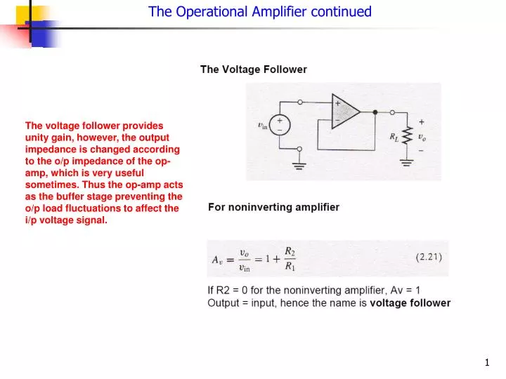
The Operational Amplifier continued The voltage follower provides unity gain, however, the output impedance is changed according to the o/p impedance of the op-amp, which is very useful sometimes. Thus the op-amp acts as the buffer stage preventing the o/p load fluctuations to affect the i/p voltage signal.
Non-inverting amplifier design: Effects of resistance choice For v0 = 10 V, output current is 1A Most op amps cannot handle such large current, so small R’s should be avoided Av = 10 = 1+R2/R1 Very large resistances tend to be unstable, and lead to coupling of unwanted signals especially at higher frequencies. Why?
Special circuits: Integrator and differentiators Therefore, These circuits are useful for automobile ignition and fuel injection
Op-Amp Imperfections in the linear range of operations • Non-ideal properties in the linear range of operation • Nonlinear characteristics • DC offsets Input and Output Impedances • An Ideal op amp has infinite input impedance and zero output impedance • A Real op amp has finite input impedance and nonzero output impedance • For IC op amps made of BJTs open-loop input impedance is about 1 MW • For IC op amps made of JFETs open-loop input impedance is about 1012W • Open loop output impedance is between 1 and 100 W • Closed loop impedances will be different, and can be chosen by proper resistors
Op-Amp Imperfections in The Linear Range of Operations Gain and Bandwidth Limitations • Ideal op amps have infinite open-loop gain magnitude (AoL is infinite), but the gain of a real op amp is finite and a function of frequency • dc open-circuit differential voltage gain is typically between 104 to 106 • The bandwidth is usually limited by the designer to prevent oscillations from feedback, by a process is called frequency compensation The open loop gain function of an op-amp usually has a single dominant pole and is given as: • AOL (f) - open-loop gain as function of frequency • A0OL - dc open-loop gain • fBOL - open-loop break frequency • AOL (f) - constant up to fBOL then it rolls off at 20 dB/decade
Gain-Bandwidth Limitations Assuming infinite input impedance and zero input current Voltage across resistor R1 (2.26) Definition of open-loop gain Hence from (2.27) Thus, Therefore, the closed-loop gain (2.27) and
For an ideal op amp But In the limit of AOL tending to infinity, This is the same result as before Op amp Closed-loop gain is given as, Putting We have, Defining and we have which is very similar in form to the open loop gain
Closed-Loop Bandwidth Substituting, and But we know that Therefore This same formula applies to a non-inverting as well as an inverting amplifier
Gain Bandwidth Product Note that you are trading off the high gain of the op-amp for a higher bandwidth
Closed-Loop Gain Versus Frequency Not that at ft the gain becomes 1