Download
1 / 23
230 likes | 390 Vues
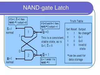
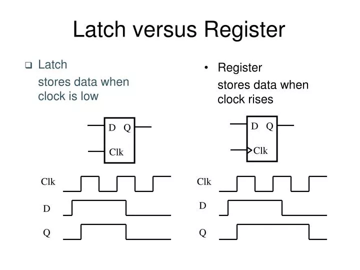
Latch versus Register. Latch stores data when clock is low. Register stores data when clock rises. D. Q. D. Q. Clk. Clk. Clk. Clk. D. D. Q. Q. Latches. Latch-Based Design. N latch is transparent when f = 0. P latch is transparent when f = 1. f. N. P. Logic.

E N D
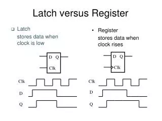
Latch versus Register • Latch stores data when clock is low • Register stores data when clock rises D Q D Q Clk Clk Clk Clk D D Q Q
Latch-Based Design • N latch is transparentwhen f = 0 • P latch is transparent when f = 1 f N P Logic Latch Latch Logic
Timing Definitions CLK Register t D Q t t su hold D DATA CLK STABLE t t c q 2 Q DATA STABLE t
V Vi2 V V i o1 1 o 2 A C B V V = = V V i i 2 1 o o 2 1 Positive Feedback: Bi-Stability 1 1 o o V V 5 2 i V 1 o V 5 2 i V
Meta-Stability Gain should be larger than 1 in the transition region
CLK D D CLK Writing into a Static Latch Use the clock as a decoupling signal, that distinguishes between the transparent and opaque states Forcing the state (can implement as NMOS-only) Converting into a MUX
Q 0 Q 1 D 1 D 0 CLK Mux-Based Latches Negative latch (transparent when CLK= 0) Positive latch (transparent when CLK= 1) CLK
Mux-Based Latch NMOS only Non-overlapping clocks
Master-Slave (Edge-Triggered) Register Two opposite latches trigger on edge Also called master-slave latch pair
Master-Slave Register Multiplexer-based latch pair
Avoiding Clock Overlap X CLK CLK Q A D B CLK CLK (a) Schematic diagram CLK CLK (b) Overlapping clock pairs
Other Latches/Registers: C2MOS “Keepers” can be added to make circuit pseudo-static
Insensitive to Clock-Overlap V V V V DD DD DD DD M M M M 2 6 2 6 M M 0 0 4 8 X X D Q D Q M M 1 1 3 7 M M M M 1 5 1 5 (a) (0-0) overlap (b) (1-1) overlap
Other Latches/Registers: TSPC Positive latch (transparent when CLK= 1) Negative latch (transparent when CLK= 0)
Including Logic in TSPC Example: logic inside the latch AND latch
Pulse-Triggered LatchesAn Alternative Approach Ways to design an edge-triggered sequential cell: Master-Slave Latches Pulse-Triggered Latch L1 L2 L Data Data D Q D Q D Q Clk Clk Clk Clk Clk
Pulsed Latches Hybrid Latch – Flip-flop (HLFF), AMD K-6 and K-7 :