Download
1 / 10
100 likes | 236 Vues
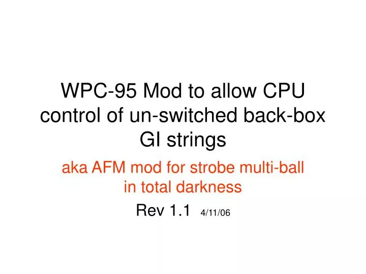
WPC-95 Mod to allow CPU control of un-switched back-box GI strings. aka AFM mod for strobe multi-ball in total darkness Rev 1.1 4/11/06.

E N D
WPC-95 Mod to allow CPU control of un-switched back-box GI strings aka AFM mod for strobe multi-ball in total darkness Rev 1.1 4/11/06
As fantastic a game as Attack From Mars is, it has one flaw that I felt needed fixing. When in strobe multi-ball, two GI strings in the back-box stay on – thus minimizing the strobe effect to a small degree. Don’t get me wrong, it’s challenging enough with the back-box lights – but without – it’s insane. For starters, AFM (other WPC-95 games as well) has two back-box GI strings that run straight off the transformer, thus are not TRIAC (CPU) controlled, or better said: un-switched. These two strings light immediately upon toggling the power switch – the rest come on after start up diagnostics are complete. Because of this un-switched condition – when strobe multi-ball is played, these two strings cannot turn off, and remain on. The same can be said for video mode – these strings do not go out. Early WPC-95 games (AFM included) came with eight diodes (D25-D32), on the driver board, that were used to drop the voltage of the two un-switched back-box strings to have the same brightness as the other GI strings in the game. Problem was, the designers did not take into consideration the heat these diodes would generate.
To perform what they wanted, heat-sinks were going to be necessary. I suspect the diodes were considered a simple/cheap solution, and a more proper solution was either not considered due to either expense or as an oversight. As a result, the diodes began to burn the driver boards in early WPC-95 games, until a service bulletin was issued to remove the diodes and replace with 0 Ω resistors, or there was a myriad of ways suggested to use jumpers. Of course, future WPC-95 games came without the diodes altogether. Instead of the resistors, one could jumper all eight positions, or follow the Marvin guide’s four jumper solution (left), or it turns out you only need two (right ). On the right you can see the rich, black color, of what should be an otherwise green PCB.
Going with the two jumper configuration gives a nice little spot of room to put, say, a relay? Yep. So we know a couple things, the two un-switched GI strings run ~ 6vac, and either string draws less than 5A. Since we have two strings, a DPDT or DPST-NO (harder to find) will work. Below is the relay I chose. It was actually hard to find a relay to the exact specs for the circuit – but being anal retentive, I found this one from a manufacturer called Sky Electronics ( www.skyrelays.com ) – through their distribution arm – Source Research ( www.sourceresearch.com ). Now this one ended up being a little bigger than I wanted, but I don’t have to do anything other than find room. Now, I will say there are a myriad of relays that could work – and most importantly DC relays are in abundance. After finishing the project, I really think finding the same relay in DC would be a better solution. HOWEVER, this will likely add an extra component in the form of a simple bridge rectifier - Radio Shack has a nice flat one that could mount onto a small relay - to convert the xfer’s AC to the relays DC coil. You may also experiment and find a DC relay (if there is an internal diode, forget it) that will work with out the rectifier. Experiment!
Next, prep the relay by installing a .062 Molex connector for the power connection, and applying Velcro. The Velcro will hold the relay to the board (or you can leave it secured elsewhere in the back-box) and the Molex connector will allow driver board removal, because power for the relay will come from J106’s IDC connector.
Attach 20-22 gauge wire to J106’s IDC connector at positions 2 & 8. These are unused on J106, but since J106 is entirely parallel to J105 you will find this is one of the switched GI power strings. Since the relay current draw is minimal, adding this to the circuit does no harm. At the end of the wire, attach the mate Molex connector to the one you put on the relay. This is the relay’s power and pseudo-CPU control. If you purchased the $7 IDC tool from ITWPancon – congrats, much easier than pushing in with a screwdriver. www.itwpancon.com Go there for free samples of these types of connectors (in small quantities) or to find distributors that sell the tools necessary to use install these connectors.
Going back to an earlier picture – these are the two jumpers the relay needs to open and close. Each jumper represents an un-switched back-box GI string. Simply remove the jumpers and replace with four individual wires at least 4” in length (you’ll cut them down later). I used two green, and two white, to avoid wiring confusion on the relay. Now a word of warning, if your board got nice and burnt you may experience trace damage – exercise caution when soldering and unsoldering as to not remove the traces/pads as you go. Below these jumpers is enough room to Velcro in about any relay for this purpose. Make sure to clean with alcohol before you apply the Velcro. Put the relay into position and wire each green to the relay common, and each white to the NO position. Remember as power is applied, this will close the contacts and connect the strings.
Here is the final product. A little big, I know – but RGP’rs will find much smaller, better relays, and find various ways to install them. But this is the first – so allow me some room for improvement. Now you can see why the Molex connector is needed – the relay is both Velcro’d and ‘wired’ to the driver board –So to remove the driver board, you have to have a way to disconnect power from the relay as power is tied to J106.
If no back-box GI during strobe multi-ball is a tad too harrowing for you, you have the option of leaving one string intact and only switching the other – so almost-total darkness. I hope you enjoy this simple mod. Please keep me up-to-date of any further evolutions of this mod – that’s the fun part. Also, let me know if this can be applied to other games as well (rumor has it CV could use this mod for ‘neon’ multi-ball). I have already found that during video mode and places in the game where the back-box flashers are activated, this mod really enhances these modes. Enjoy and thanks! Matt “Sonic” Masters mattmasters@insightbb.com
Rev 1.1 Update: After much time playing my AFM with this mod, it occurred to me that there was a rather annoying by-product that I had not originally accounted for. At different points in the game, the GI string that feeds the relay, dims. This will cause ‘chatter’ on the relay. There is no harm in this (possibly shortened relay lifespan), it simply is annoying. To fix this, simply install a diode and a capacitor (good thing I put in that Molex connector so that I could experiment!). A 2200µf electrolytic capacitor across the relay power, and a 1N400X (X=1-7, whatever you have laying around will be fine) diode in series with the relay power as long as the band (cathode) is toward the relay and oriented to the + (positive) lead of the capacitor. See schematic below: + J106