Download
1 / 13
130 likes | 247 Vues
Trasmission lines. Lightwave Analogy to RF Energy. Incident. Transmitted. Reflected. Lightwave. DUT. RF. Why Do We Need to Test Components?. Verify specifications of “building blocks” for more complex RF systems Ensure distortionless transmission of communications signals

E N D
Lightwave Analogy to RF Energy Incident Transmitted Reflected Lightwave DUT RF
Why Do We Need to Test Components? • Verify specifications of “building blocks” for more complex RF systems • Ensure distortionless transmission of communications signals • linear:constant amplitude, linear phase / constant group delay • nonlinear: harmonics, intermodulation, compression, AM-to-PM conversion • Ensure good match when absorbing power (e.g., an antenna)
S21 S11 S22 S12 Mag Time High-frequency transistor model Base Collector Error Measured Emitter Actual The Need for Both Magnitude and Phase 1. Complete characterization of linear networks 2. Complex impedance needed to design matching circuits 4. Time-domain characterization 3. Complex values needed for device modeling 5. Vector-error correction
Transmission Line Basics - + I Low frequencies • wavelengths >> wire length • current (I) travels down wires easily for efficient power transmission • measured voltage and current not dependent on position along wire High frequencies • wavelength » or << length of transmission medium • need transmission lines for efficient power transmission • matching to characteristic impedance (Zo) is very important for low reflection and maximum power transfer • measured envelope voltage dependent on position along line
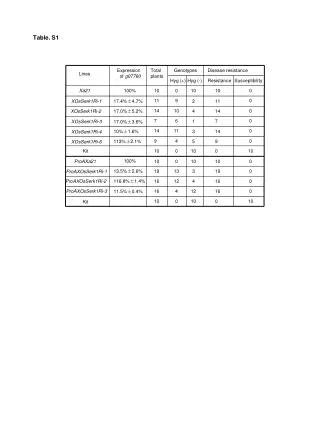
1.5 attenuation is lowest at 77 ohms 1.4 1.3 1.2 50 ohm standard 1.1 normalized values 1.0 0.9 0.8 power handling capacity peaks at 30 ohms 0.7 0.6 0.5 10 20 30 40 50 60 70 80 90 100 characteristic impedance for coaxial airlines (ohms) Transmission line Zo • Zo determines relationship between voltage and current waves • Zo is a function of physical dimensions and r • Zo is usually a real impedance (e.g. 50 or 75 ohms)
RS RL 1.2 1 0.8 Load Power (normalized) 0.6 0.4 0.2 0 0 1 2 3 4 5 6 7 8 9 10 Power Transfer Efficiency For complex impedances, maximum power transfer occurs when ZL = ZS* (conjugate match) RL / RS Maximum power is transferred when RL = RS
V inc Transmission Line Terminated with Zo Zo = characteristic impedance of transmission line Zs = Zo Zo Vrefl = 0! (all the incident power is absorbed in the load) For reflection, a transmission line terminated in Zo behaves like an infinitely long transmission line
V inc Transmission Line Terminated with Short, Open Zs = Zo In-phase (0o) for open, out-of-phase (180o) for short Vrefl For reflection, a transmission line terminated in a short or open reflects all power back to source.
V inc Transmission Line Terminated with 25 W Zs = Zo ZL = 25 W Vrefl Standing wave pattern does not go to zero as with short or open
A Reflected = R Incident High-Frequency Device Characterization Incident Transmitted R B Reflected A TRANSMISSION REFLECTION B Transmitted = R Incident Group Return SWR Gain / Loss Delay Loss Insertion S-Parameters Impedance, Admittance S-Parameters S11, S22 Phase Reflection Transmission S21, S12 Coefficient R+jX, G+jB Coefficient G, r T,t
Reflection Coefficient G - r V Z Z = = F = reflected O L V Z Z + incident r O L G Return loss = -20 log(r), = Emax Emin 1 + r Emax VSWR = = 1 - r Emin r RL VSWR Reflection Parameters Voltage Standing Wave Ratio Full reflection (ZL = open, short) No reflection (ZL = Zo) 1 0 ¥dB 0 dB ¥ 1
V Transmitted V Transmitted V Incident V Trans V Inc V Trans V Inc Transmission Parameters V Incident DUT T = tÐf Transmission Coefficient = = = - 20 log t Insertion Loss (dB) = - 20 Log Gain (dB) = 20 Log = 20 log t