Download
1 / 13
130 likes | 132 Vues
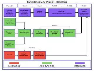
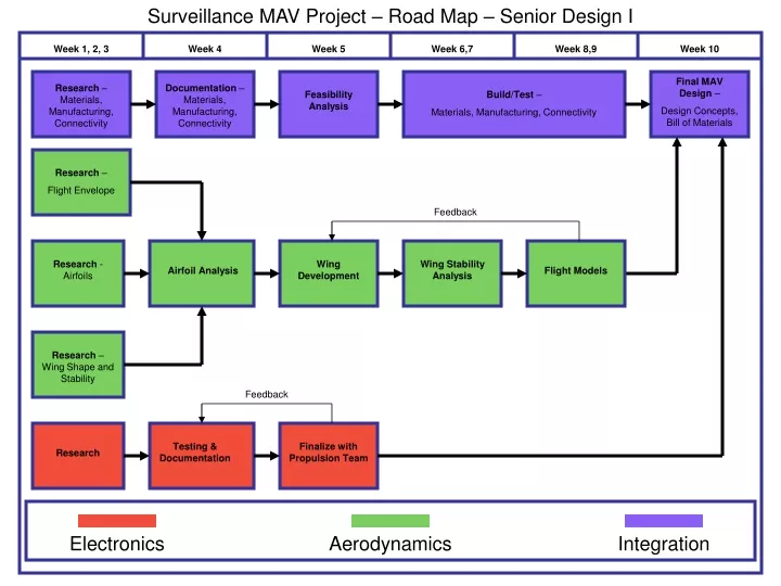
This project aims to design and build a surveillance Micro Aerial Vehicle (MAV) that can fly up to 1.2 kilometers, capture clear photos, and be controlled remotely. The roadmap includes research, materials analysis, wing development, propulsion integration, and testing. The objectives include stability, endurance, connectivity, and manufacturability.

E N D
Surveillance MAV Project – Road Map – Senior Design I Week 1, 2, 3 Week 4 Week 5 Week 6,7 Week 8,9 Week 10 Final MAV Design – Design Concepts, Bill of Materials Research – Materials, Manufacturing, Connectivity Documentation – Materials, Manufacturing, Connectivity Feasibility Analysis Build/Test – Materials, Manufacturing, Connectivity Research – Flight Envelope Feedback Research - Airfoils Wing Development Wing Stability Analysis Airfoil Analysis Flight Models Research – Wing Shape and Stability Feedback Testing & Documentation Finalize with Propulsion Team Research Electronics Aerodynamics Integration
Surveillance MAV Project – Road Map – Senior Design II Week 1, 2, 3 Week 4 Week 5 Week 6,7 Week 8,9 Week 10 Research – Materials, Manufacturing, Connectivity Feedback Feedback Electronics Aerodynamics Integration
Surveillance MAV Project – Gantt Chart – Senior Design I W 1 W 2 W 3 W 4 W 5 W 6 W 7 W 8 W 9 W 10 Research – Flight Envelope Research – Airfoils Research – Wing Shape and Stability Aerodynamics Airfoil Analysis Wing Development Wing Stability Analysis Flight Models Research Electronics Testing & Documentation Finalize with Propulsion Team Research – Materials, Manufacturing, Connectivity Documentation – Materials, Manufacturing, Connectivity Integration Feasibility Analysis Build/Test – Materials, Manufacturing, Connectivity Final MAV Design – Design Concepts, Bill of Materials
Surveillance MAV Project – Objectives List Necessary Desirable Able to fly 600 meters (linear) Able to fly 1.2 kilometers or more Able to take a “legible” picture of a 1.5 square-meter symbol located on the ground Able to rotate camera Autonomous flight Wireless remote control (human operator) GPS Stability Augmentation System Stay within budget (~$4500) Use Fall/Winter Senior Design Team’s Propulsion System/Data Stable, consistent launching Able to be flown accurately 500 meters from the target symbol MAV able to be reproduced consistently Must be durable Smallest possible maximum linear dimension Must be able to deliver a hard copy of the photo to judges within 45 minutes of launch Lightest possible weight Black and white photo Color photo Onboard power supply Capture and record video onboard Capture and transmit live video
Surveillance MAV Project – Objective Tree The MAV must complete the mission outlined by the IMAVC. Electronics Aerodynamics Integration MAV Picture Stability Size Propulsion Lift/Drag Remote Control Endurance Size Size Manufacturability Endurance Endurance Connectivity See Requirements See Requirements See Requirements
Surveillance MAV Project – Requirements Aerodynamics Integration Electronics Stability Picture • Must be stable in pitch, yaw, roll • Aircraft will have a positive pitching moment intercept and a negative slope • Elevons shall be effective in controlling pitch rates • Aircraft shall be critically damped in yaw direction • Aircraft yawing moment curve must be positive and 0 intercept • Aircraft shall have a negative rolling moment and 0 intercept • Elevons shall be effective in controlling roll rates • Force on control surfaces shall not exceed force provided by servo • The CG shall be located to ensure stability • Elevon operation shall have minimal effect on yaw Size • Take photo • Record photo • Transmit photo • Receive photo • As small and compact as possible, but still able to carry all necessary components Propulsion Endurance - Minimize power consumption • Drop test (10’ vertical drop) • Static load test • Failure • Pod shock/compression test • ANSYS models Remote Control • Radio • Receiver Lift/Drag Manufacturability - Planform must minimize tip vortices • Construction tools • Feasibility • Material documentation/knowledge/experience Size Size - As small and compact as possible (within the scope of the project) - Planform that optimizes lift for small maximum linear dimension Connectivity Endurance Endurance • Connect wing to pod • Shear landing test • Sufficient battery • Lasting parts - Maintain stability/lift/drag for the duration of the flight
Surveillance MAV Project – Specifications Aerodynamics Integration Electronics Stability Picture Size • Camera Resolution: > 300 lines • - Cmo > 0 • Cmα < 0 • Cmδev > ? • ξn < 0 • Cn0 = 0 • Cn > 0 • Clδev > ? • N.P. < Xcg • Span Efficiency Factor e > ? • Capable of holding 60 g in minimal volume Propulsion • Power Supplied: 450 mA; 11 V • Thrust Supplied: 70 g Endurance Remote Control • Drop Test: MAV must withstand 10 ft vertical drop (from tail, left/right wing, nose, and center) with no apparent damage • Static Loading Test: MAV must withstand suspension from outer wing tips, loading with “factor of safety” of 1.5, with no apparent damage • Maximum Dynamic Loading Test: MAV attached to rod through CG, exposed to simulated flight speeds until time of fatigue • Dynamic Rate Test: Using dynamic test stand with incorporated ball/socket joint, attach 0.02 inch diameter carbon rods to nose, left/right wings, test dynamic rolling/pitching rates by measuring vertical displacement of carbon rods • Transmitter Frequency: 2.4 GHz • Transmitter RF Power Output: 80 mW • Receiver Frequency: 2.4 GHz • Receiver Gain: 20 db • Receiver Impedance: 50 ohms • Antenna Frequency: 2.4 GHz • Antenna Gain: 8 dbi • Antenna Beam Width: 8º • Antenna Impedance: 50 ohms Lift/Drag Size • Camera Dimensions: 20 x 20 x 15 mm • Camera Weight: 5.5 g • Transmitter Dimensions: 15 x 15 x 5 mm • Transmitter Weight: 3 g • Servo Dimensions: 300 x 100 x 200 mm • Servo Weight: 4.3 g • Propulsion System Dimensions: ??? • Propulsion System Weight: ??? Size Manufacturability • Span b <= 25.4 cm • AR > 1 • Rapid Prototyping Resolution: Up to 0.03 inches • Machining Precision: Up to 0.005 inches Connectivity Endurance Endurance • Camera Power Consumption: 420 mW • Transmitter Power Consumption: 210 mW • Servo Power Consumption: 1 W • Shearing: Perform compression test to determine shear strength of connection between wing/pod - Minimum Flight Thrust = x
Surveillance MAV Project – Morphological Analysis 04 06 01 02 03 05 07 08 09 10 11 12 Remote Control (Computer/Human Operator) Autonomo-us None Remote Control (Human Operator) Stability Augmenta-tion Control Lithium Polymer Battery Gas Microturbi-ne Alkaline Batteries Capacitor Power Camera with Film Storage Camera with Digital Storage Camera with Transmitter Infrared Camera with Transmitter Night Vision Camera with Transmitter Movable Camera with Transmitter Camera System Shrink-wrap Tissue Paper Parylene-C Resin/Epo-xy Mylar Durobotics Fabric Polymers Latex Chemical Resin Dip Fiberglass Skin Compress-ed Air Electric Motor/Pro-pellor Gas Motor/Pro-pellor Ornithopter Electric Motor/Pro-pellor/Shr-oud Propu-lsion Polymers Rapid Prototyping Durobotics Kevlar Carbon Fiber Fiberglass Composite Rods Composite Tow Kevlar/Ca-rbon Combo Titanium Alloy Balsa Foam Wing/ Pod Rudder Spoilers Morphing Thrust Vectoring (Drag) Differential Morphing Elevon Movable C.G. None Flight - Yaw Thrust Elevator Elevons Thrust Vectoring Morphing Movable C.G. Flight - Pitch Elevons Morphing Flaperons Ailerons Thrust Vectoring Spoilers Movable C.G. Flight - Roll
Surveillance MAV Project – QFD Analysis (Phase I) Weight (g) Key Dimensions (cm) 3 0 = not correlated 1 = slightly correlated 3 = correlated 9 = highly correlated Resolution (lines) 0 0 Power (mAh) 9 1 1 Thrust (g) 1 0 9 1 RF Power (mW) 0 0 0 1 0 Optimization Voice of the Customer Engineering Metrics Customer Requirements Dimensions (cm) Customer Weight Weight (g) Power (mAh) Thrust (g) Resolution (lines) RF Power (mW) 9 1 1 0 9 9 0 Able to fly 600 meters (linear) 9 0 0 9 3 0 1 Able to take a “legible” picture 9 0 0 0 9 0 9 Wireless remote control Key 3 1 1 3 3 1 1 Stay within budget 0 = not important 1 = slightly important 3 = important 9 = very important 9 3 3 0 1 3 0 Stable, consistent launching unnecessary 3 3 3 0 1 3 1 Able to be flown accurately 3 3 1 0 0 1 0 Must be durable 9 0 0 1 1 0 9 Must provide hard copy of photo 9 3 3 1 9 3 3 Onboard power supply Technical Target 300 65 80 100 25.4 380 Raw Score 84 108 300 150 78 204 Relative Weight .09 .08 .12 .32 .16 .22
Surveillance MAV Project – QFD Analysis (Phase II) MAV Parts Phase I Relative Weights Wing Pod Propulsion System Camera System Servos Engineering Metrics Weight (g) .09 1 1 9 3 1 Dimensions (cm) Key .08 9 1 1 1 0 Resolution (lines) 0 = no contribution .12 0 0 0 9 0 1 = slight contribution Power (mAh) 3 = notable contribution .32 0 0 9 9 3 9 = large contribution Thrust (g) .16 0 0 9 0 0 RF Power (mW) .22 0 0 3 3 3 Raw Score .81 .17 5.87 4.97 1.71 Relative Weight .06 .01 .43 .37 .13
Surveillance MAV Project – Pugh Analysis (page 1) Sub-Functions Design Concepts 01 02 03 04 Control Remote Control (Human Operator) Remote Control (Human Operator) Remote Control (Human Operator) Remote Control (Human Operator) Power Lithium Polymer Battery Lithium Polymer Battery Lithium Polymer Battery Lithium Polymer Battery Camera System Camera with Transmitter Camera with Transmitter Camera with Digital Storage Movable Camera with Transmitter Skin Parylene-C Shrink-wrap Fiberglass Latex Propulsion Electric Motor/Propeller Electric Motor/Propeller Electric Motor/Propeller/Shroud Electric Motor/Propeller Wing/Pod Carbon Fiber Carbon Fiber Fiberglass Foam Flight - Yaw None Rudder None Rudder Flight - Pitch Elevons Elevons Morphing Elevons Flight - Roll Elevons Elevons Morphing Elevons Design Concepts Design Concepts Criteria Criteria 01 02 03 04 01 02 03 04 Able to fly 600 meters (linear) + + + Able to fly 600 meters (linear) - - S REFERENCE REFERENCE Able to take a “legible” picture S S + Able to take a “legible” picture S S S Wireless remote control S S S Wireless remote control S S S Stay within budget - - - Stay within budget + - - Stable, consistent launching unnecessary + - + Stable, consistent launching unnecessary - - S Able to be flown accurately + S + Able to be flown accurately - - S Must be durable S - - Must be durable S - - Must provide hard copy of photo S - S Must provide hard copy of photo S - S Onboard power supply S S S Onboard power supply S S S # +’s 3 1 4 # +’s 1 0 0 Score # S’s 5 4 3 Score # S’s 5 3 7 # -’s 1 4 2 # -’s 3 6 2
Surveillance MAV Project – Pugh Analysis (page 2) Sub-Functions Design Concepts 01 02 03 04 Control Remote Control (Human Operator) Remote Control (Human Operator) Remote Control (Human Operator) Remote Control (Human Operator) Power Lithium Polymer Battery Lithium Polymer Battery Lithium Polymer Battery Lithium Polymer Battery Camera System Camera with Transmitter Camera with Transmitter Camera with Digital Storage Movable Camera with Transmitter Skin Parylene-C Shrink-wrap Fiberglass Latex Propulsion Electric Motor/Propeller Electric Motor/Propeller Electric Motor/Propeller/Shroud Electric Motor/Propeller Wing/Pod Carbon Fiber Carbon Fiber Fiberglass Foam Flight - Yaw None Rudder None Rudder Flight - Pitch Elevons Elevons Morphing Elevons Flight - Roll Elevons Elevons Morphing Elevons Design Concepts Design Concepts Criteria Criteria 01 02 03 04 01 02 03 04 Able to fly 600 meters (linear) - + + Able to fly 600 meters (linear) - S - REFERENCE REFERENCE Able to take a “legible” picture S S S Able to take a “legible” picture S S S Wireless remote control S S S Wireless remote control S S S Stay within budget + + S Stay within budget + + S Stable, consistent launching unnecessary + + - Stable, consistent launching unnecessary - S - Able to be flown accurately - + + Able to be flown accurately - S - Must be durable + + - Must be durable + + + Must provide hard copy of photo + + + Must provide hard copy of photo S S - Onboard power supply S S S Onboard power supply S S S # +’s 4 6 3 # +’s 2 2 1 Score # S’s 3 3 4 Score # S’s 4 7 4 # -’s 2 0 2 # -’s 3 0 4