Download
1 / 24
250 likes | 308 Vues
Bronze C Theory. The Principles of Flight. Terms Wing Section Chord line Mean Camber line Airflow Relative Airflow Boundary layer Stagnation point Angle of Attack (AoA) Typically 0 to 12 degrees AoA drawing.

E N D
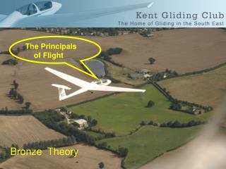
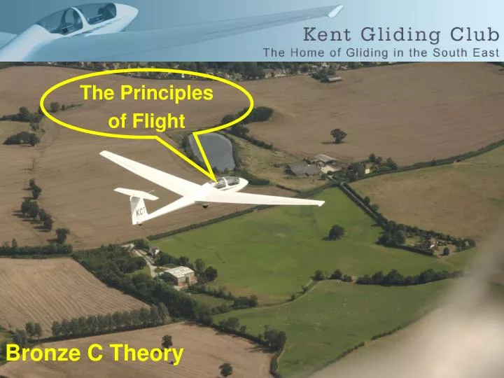
Bronze C Theory The Principles of Flight
Terms Wing Section Chord lineMean Camber lineAirflow Relative Airflow Boundary layerStagnation point Angle of Attack (AoA)Typically 0 to 12 degreesAoA drawing
Increase Lift by increasing speed or AoA The forces are balanced unless accelerating.Main couple.
Lift increases with AoA until the critical angle is reached when the airflow can no longer flow smoothly over the wing’s upper surface. The point on the wing where the air becomes turbulent is known as the transition point
If we exceed this angle lift reduces sharply. The wing has now stalled. We have reached the stalling angle.
2/3 of the lift generated comes from the upper surface and 1/3 from the lower surface. Lift distribution diagram
To keep it simple think of the lift force acting through one point which is known as the centre of pressure. This force acts perpendicular to the chord line.
This CP moves forward and back as the AoA increases or decreases in the normal range.
Increase Lift by increasing speed or AoA. This was slide three. Here is an interesting point to consider. If we fill the wing with water we must fly faster to generate enough lift. The glide performance remains thesame but at a higher speed.Next - stall
In the classic stall the CP moves rapidly from the leading edge at the critical angle and attaches to the trailing edge - producing the marked nose down pitch.
We now know the glider produces lift when it goes through the air. In a steady state this forward motion is opposed by Drag. If the glider continued to accelerate the force would increase beyond the strength of the airframe and so a limit is imposed. This is called VNE. Velocity Never Exceed.
While we are on the subject of Speed, here is a picture of a typical Air Speed Indicator.We need to know what the coloured arcs mean.
Drag is comprised of different elements. The overall force is known as Total Drag. This is comprised of Profile and Induced drag
Profile drag is made up of Form Drag and Skin FrictionForm Drag is caused by the physical shape of the glider.Form drag includes Interference drag which is caused by airflow meeting at sharp junctions, wings and fuselage etc.
As the name suggests Skin Friction is caused by the relative smoothness of the wings surface (laminar flow)Induced drag is lift related and it reduces as speed increases. Induced Drag is also load related, as load increases so does the lift related drag. Vortices. Winglets
When discussing the forces in flight the Lift force is considered to be at 90 deg to the Relative AirflowDrag is parallel to the Relative AirflowWeight always acts vertically downResolution of forces Diagram
Earlier we discussed the Stall. If we now consider the wings as two separate items, we can see that if one wing is going slower than the other, it is possible for one wing to stall before the other. At slow speed Yaw can cause this and precipitate a spin.In a spin the inner wing is going slower and is in a deeper stall, which produces more drag than the outer wing. This extra drag causes the glider to continue to rotate or “Autorotate”.
So now we have to considered that the ailerons can produce different amounts of drag from each other.Alieron Drag/Adverse yaw.Differential Ailerons. The down Aileron moves much less than the up Aileron.
We must now consider how we control the glider in Pitch.We do this by increasing or decreasing the lift generated by the tailplane to achieve the attitude we want.
The stability of the glider can be affected by the cockpit load. If we reduce the cockpit load the C of G will move aft and the longitudinal stability will reduce. On the other hand if we increase the cockpit load the C of G will move forward and we could run out of elevator authority and be unable to raise the nose.
One final point I want to cover is the question of Compass errors. In the northern hemisphere a normal panel type ball compass will show a turn to the North when you accelerate and South when you decelerate.
A basic compass also has a lag during part of a turn and a lead during the opposite part. For this reason to come out of a turn on a set heading, “undershoot to the North” & “overshoot to the South”. If you want to come out on North exit the turn 30 deg early. If you want to leave the turn on South leave 30 deg late. No adjustment East/West