Download
1 / 50
500 likes | 676 Vues
Image and Video Compression (cont.). Wenwu Wang Centre for Vision Speech and Signal Processing Department of Electronic Engineering University of Surrey Email: w.wang@surrey.ac.uk. Subband and Wavelet Coding. Motivation.

E N D
Image and Video Compression(cont.) Wenwu Wang Centre for Vision Speech and Signal Processing Department of Electronic Engineering University of Surrey Email: w.wang@surrey.ac.uk
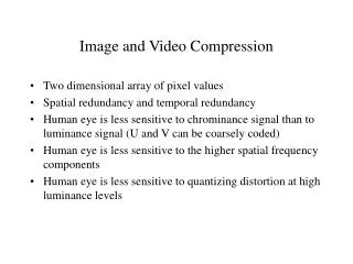
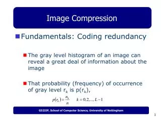
Motivation • Natural images tend to have a non-uniform frequency spectrum with most of the energy being concentrated on lower bands. • Human perception of noise tends to fall off at high and low frequencies and this enables the designer to adjust the compression distortion according to perceptual criteria. • Since images are processed in their entirety and not in artificial blocks, there is no block structure distortion in the coded picture, as occurs in the block-transform-based image coders, such as DCT.
Motivation (cont.) • Compared to Fourier transform, in subband coding, filter banks have a better decorrelation property that suits natural images better. Fourier basis functions are very exact in frequency, but are spatially not precise. The signal energy is not concentrated on one frequency but spread over all space. This is not a problem if pixels are correlated, but is a problem across the edges. Subband bases not only have good frequency concentration, but also spatially compact.
Example of 2-D Band Scheme Filtering: Downsampling:
Example of 2-D Band Scheme (cont.) • Half-band filters would be typically used: low-pass filter and high-pass filter. • This allows 2:1 downsampling to be applied to each of the two filtered versions of the input. • Coding: quantisation and entropy coding of each subband. • Decoding: entropy decoding and inverse quantisation. • Interpolative upsampling at the synthesis stage. • Interpolated subbands added together to form a reconstructed version of the source image.
Filter Design Issues • For the 2-band example, the optimal analysis filterbank would be the ideal unity gain low-pass and high-pass filters. • These are unrealisable in the spatial domain as they would require an infinite number of coefficients. If implemented in the frequency domain they would result in severe ringing (ripples across sharp transitions) in subbands. • The frequency responses of practical filters are overlapping which means that aliasing of spatial frequencies in the overlap region (shaded) is unavoidable (fs is the sampling frequency).
Filter Design Issues (cont.) • One of the objectives of filter design for subband coding is the cancellation of aliasing at the synthesis stage • Although individual subbands are aliased it is possible to achieve cancellation of this effect when adding the subbands together for reconstruction during the synthesis stage. • Typically, if the phases of the aliased components from the high and lowpass subbands can be made to differ by 180o, then the cancellation occurs and the recovered signal is alias free. • A class of filters specifically designed to achieve alias cancellation is called Quadrature Mirror Filters (QMFs).
Quadrature Mirror Filters • A 2-band system in the z-domain: • Output of the analysis filterbank: • Output of the synthesis bank (after summing):
Quadrature Mirror Filters (cont.) • Reconstructed signal ignoring the coding effects: • The second term represents the aliased component which can be set to zero using appropriate analysis and synthesis filter choices. If
Quadrature Mirror Filters (cont.) If we define: Then: where is called product filter. If: Then the reconstructed signal can be a perfect, but an m-sample delayed replica of the input signal, i.e. the reconstructed pixel sequence is an exact replica of the input sequence but delayed by m pixels.
2-D Subband Decomposition • The 2-D decompositions are straightforward extensions of the 1-D cases: • Variable-separable (first horizontal, then vertical) filtering is a popular choice for implementation • Horizontal subsampling is performed after horizontal filtering so that the number of vertical filtering operations is halved • A 2-band 1-D scheme applied twice in cascade (i.e. first horizontally then vertically) yields 4 subbands as shown below (analysis part):
2-D Subband Decomposition (cont.) • The equivalent partition of the 2-D spatial frequency spectrum is shown below:
Multiband Decompositions • M-channel filterbanks using different filters for each band can be used to achieve a multiband decomposition: • A popular such design is called uniform DFT bank and uses filters whose frequency responses are uniformly shifted version of the response of a prototype low-pass filter. • This achieves a parallel decomposition of the input signal to M subbands of equal bandwidth.
Multiband Decompositions (cont.) • The above readily generalises to 2-D by cascading horizontal and vertical filtering in a variable-separable way • A fixed tiling of the 2-D spatial frequency spectrum is achieved.
Generalised Multiband Decompositions • More complex partitions of the spatial frequency spectrum can be achieved by iterating the 2-D decomposition process. • In the following diagram, each of the 4 initial subbands can be further decomposed by iteratively applying the same analysis filterbank • Each branch represents a filter-and-subsample stage. The 1-input, 4-output unit shown in a dashed frame corresponds to the variable-separable 2-D analysis filterbank discussed ealier. • In the spatial frequency domain, this amounts to a quad-tree decomposition. Such complex partititions are widely used in wavelet coding schemes.
Coding of Subbands • The lowest frequency (DC) subband is a subsampled replica of the original • Typically, it contains more than 95% of the source image energy, and is usually coded separately from other subbands • The other (AC) subbands contain high-frequency information (e.g. image edges) • Edge information is distributed among subbands according to strength and orientation, and very high-frequency bands have nearly white power spectral density • Coding of subbands can be performed either by considering each subband separately (intraband coding) or by suitably combining information from two or more subbands (interband coding). Intraband coding may provide greater immunity to errors as they will be confined to a single subband, while interband coding may be more efficient in terms of compression.
Intraband Coding • Elements within the same subband are coded using: element-to-element prediction followed by scalar quantisation of the prediction error, followed by entropy coding. • Predictive coding (PCM) has been reported to give good results for the DC subband where pixel-to-pixel correlation is still high. • Either DPCM or PCM is a good choice for coding the AC subbands.
Interband Coding • Suitable collections of elements from different subbands (typically from neighbouring spatial locations) are coded together. • Such blocks can be either used as vectors suitable for VQ coding, or scalar-quantised, zig-zag scanned and entropy coded using a similar approach to that employed for block-transform coding. • More complex elements collections are used in wavelet coding and will be discussed later.
Relationship to Transform Coding • Both tranform-based coding and subband-based decomposition lead to representations of an image which are localised in space and spatial frequency • In subband coding: the space localisation is determined by the aperture of the filters used; frequency localisation is determined by the frequency response of those filters (or equivalently by the number of subbands) • In block transform coding: space localisation is determined by the block size; frequency localisation is determined by the resolution (i.e. length) of the basis functions used (or equivalently by the block size). • Both techniques can be viewed as filtering operations: in subband coding, filtering is applied to in the standard convolutional manner, while in block transform coding, filtering is confined to the boundaries of a block.
Performance • Subband coding is a powerful compression technique offering good picture quality at low bit-rates • One of its main advantages is the complete lack of blocking artefacts in the reconstructed pictures. • Another attractive feature is scalability which is achieved “for free” at the analysis stage. • At very low bit-rates, ringing at the vincinity of sharp transitions can become a problem due to the coarse quantisation of higher-frequency subbands. • Good separation of frequency bands requires long filters in the spatial domain which may contribute significantly to computational complexity.
Wavelet Coding • As the name implies a wavelet is a function which is localised and oscillating i.e. a wave enclosed in a decaying envelope: • There are a number of different ways to describe how signals are analysed using wavelets: • As a linear expansion in which wavelets are the required expansion bases. In that sense wavelet coding is closely related to transform coding in that it provides an alternative method for the design of the basis functions. • As a filtering operation in which wavelets are used to derive the impulse responses of the filters being used. In that sense wavelet coding is closely related to subband coding in that it provides an alternative method for filter design.
Wavelet Coding • In wavelet analysis there are two functions of interest: • The mother wavelet • The scaling function • Dilated and translated versions of those functions i.e. are associated with the design of low- and high- pass filters h(k) and g(k) respectively. • The precise nature of this “association” is the topic of the so-called iterated filterbank theory where it is shown that under particular assumptions and are limiting expressions of h(k) and g(k). • It can be shown that h(k) and g(k) can be used in a subsample-and-filter tree configuration similar to that used for subband coding.
Wavelet Basis Functions • The problem with orthonormal bases is that they do not yield linear-phase filters which are desirable in image processing • Lack of linear phase results in visible distortion in the vicinity of image edges and sharp transitions. • The only linear phase FIR filters with perfect reconstruction property associated with orthonormal bases are those corresponding to the Haar basis • h(0)=h(1)=g(0)=21/2 and g(1)=-21/2 with all other coefficients being zero. • These unfortunately have poor frequency separation characteristics. • It is possible to resolve this problem by constructing basis functions which are linearly independent but not orthonormal • These are called bi-orthogonal and yield filters with linear-phase characteristics. • The requirement for perfect reconstruction implies that low-pass analysis filters are delayed and reflected versions of the corresponding high-pass synthesis filters and vice versa
Quad-Tree Decomposition • Filters h(k) and g(k) derived from bi-orthogonal wavelet bases are used in a filterbank configuration similar to subband coding. A popular filterbank configuration is the hierarchical quad-tree shown below: • Each element of the resulting subbands is often referred to as a wavelet coefficient. • Wavelet subbands of the quad-tree decomposition are logarithmically spaced apart which is in agreement with many models of human vision perception.
Tiling of the Space-Frequency Domain • Signal decompositions resulting from iterated wavelet filtering achieve a variable partition of the space-frequency domain • High-frequency features such as edges are resolved using a narrow aperture in the space domain (only one level of subsampling employed) • Low-frequency details are solved with a narrow aperture in the frequency domain • In transform-based (DCT, DFT) techniques, the space aperture is very wide (i.e. depends on the block size) and the frequency aperture is very narrow (i.e. depends on harmonics whose spacing is also depends on the block size), both apertures are fixed (i.e. they do not adapt to the characteristics of the signal).
Coding of Wavelet Coefficients • As in subband coding, wavelet coefficients can be coded • Either within the boundaries of the same subband (intraband coding) • Or in suitable combinations with elements from other subbands (i.e. in a predictive or joint coding fashion – interband coding) • In both cases one of the following techniques are used: • Scalar quantisation followed by entropy coding • Vector quantisation • Quad-tree coding • A particularly powerful technique combining iterative scalar quantisation and quad-tree coding is the Embedded Zerotree Wavelet scheme discussed next
Embedded Zerotree Wavelet (EZW) Algorithm • What is embedded coding ? • Representing a sequence of binary decisions that distinguish an image from the “null” image • Similar in spirit to binary finite-precision representations of real numbers • What is Zerotree ? • Zerotree is based on an empirically true hypothesis i.e. decaying spectrum hypothesis:Insignificant parents (at a coarser scale) are likely to have on average insignificant descendants (at a finer scale). If the coefficient is smaller than a pre-determined threshold (yardstick), it is regarded as “insignificant”. • A tree is formed by combining the co-sited elements (i.e. with the same orientation) belonging to different subbands.
EZW (cont.) The algorithm is actually based on two concepts: • successive approximate quantisation (SAQ) • similarities among the bands of the same orientation
Parent-child dependencies of subbands EZW (cont.)
Scanning order of the subbands EZW – The Dominant Pass • Coefficients are scanned according to a predetermined order from one subband to the next as shown above.
EZW – The Dominant Pass Flow chart of encoding a coefficient of the significance map in the dominant pass
EZW – The Subordinate Pass • The dominant pass is followed by a subordinate pass • The threshold T used for quantisation purposes is halved. • The coefficients which previously have not been reconstructed as zero are scanned again according to their order in the subordinate list, and each one has added to it either T/2 or -T/2 in order to minimise the magnitude of its reconstruction error. • The dominant pass is then repeated after the subordinate pass, and the whole process is stopped when the size of bit stream exceeds the desired bit rate budget.
49 10 63 -34 -12 7 7 13 14 -13 -31 23 3 4 6 -1 3 -12 15 14 5 -7 3 9 -9 -7 -14 8 4 -2 3 2 -1 47 -2 2 -5 9 4 6 3 0 -3 2 3 -2 0 4 3 6 2 -3 3 6 6 4 5 11 0 3 5 6 -4 4 Example EZW - A Simple Example • Only string of symbols shown (No adaptive arithmetic coding) • Simple 3-scale wavelet transform of an 8 X 8 image • T0 = 32 (largest coefficient is 63)
4910 63-34 -12 7 7 13 14 -13 -31 23 3 4 6 -1 3 -12 15 14 5 -7 3 9 -9 -7 -14 8 4 -2 3 2 -1 47 -2 2 -5 9 4 6 3 0 -3 2 3 -2 0 4 3 6 2 -3 3 6 6 4 5 11 0 3 5 6 -4 4 Example EZW - A Simple Example (cont.) • First dominant pass
EZW - A Simple Example (cont.) • First subordinate pass Magnitudes are partitioned into the uncertainty intervals [32, 48) and [48, 64), with symbols “0” and “1”.
Why We Need Another Standard? • New changes in the digital image industry since JPEG was introduced in 1980s • Current demands for compressed still images range from web logos of sizes less than 10 Kbytes to high quality scanned images of sizes of 5 Gbytes. • Scalability and interoperability requirements of digital imagery in a heterogeneous network of ATM, Internet, mobile, etc.
Why We Need Another Standard? (cont.) • JPEG2000 aims to provide the best quality or performance and capabilities to market evolution that current JPEG fails. • Applications • Internet, colour facsimile, printing, scanning, digital photography, remote sensing, mobile, medical imagery, digital libraries/achieves and e-commerce
Features to Deliver • Superior low bit rate performance • offer performance superior to the current standards at low bit rates (e.g. 0.25 bit per pixel) • Applications include image transmission over networks and remote sensing. • Continuous tone and bilevel compression • It achieves this with similar system resources. It should compress and decompress images with various dynamic ranges (e.g. 1 bit to 16 bits). • Applications include: compound documents with images and texts, medical images with annotation overlays, facsimile, etc.
Features to Deliver (cont.) • Progressive transmission by pixel accuracy and resolution • Allows the reconstruction of images with different resolutions and pixel accuracy, as needed or desired, for different target devices. • Applications include web browsing, image archiving and printing. • Region of interest coding • Allows a user defined region of interest (ROI) in the image to be randomly accessed and/or decompressed with less distortion than the rest of the image, if the ROI is more important than others.
Features to Deliver (cont.) • Robustness to bit errors • It is desirable to consider robustness to bit errors while designing the code stream, by using error confinement, error concealment, or source channel coding scheme. • Applications include wireless communication channels. • Open architecture • Open architecture can be used to optimise the system for different image types and applications. • The decoder is only required to implement the core tool set and a parser that understands the code stream.
Features to Deliver (cont.) • Protective image security • Protection of a digital image can be achieved by, e.g., watermarking, labelling, stamping, fingerprinting, encryption, scrambling, etc. • Watermarking and fingerprinting are invisible marks set inside the image content to pass a protection message to the user. • Labelling is already implemented in some image formats such as SPIFF. • Stamping is a mark set on top of a displayed image that can be removed by a specific process. • Encryption and scrambling can be applied on the whole image file or limited to part of it to avoid unauthorised use of the image.
JPEG2000 – General Scheme input Preprocessing Core encoding Postprocessing output
Preprocessing • Tiling • Partitioning the image into rectangular nonoverlapping pixel blocks, known as tiling. The tile size is arbitrary and can be from the whole image to a single pixel. • Benefits include: reducing memory requirements; any part of the image can be accessed and processed differently from the other parts of the image. • Disadvantage: the correlation between the pixels in adjacent tiles is not exploited, as the title size is reduced, the compression gain of the encoder is also reduced.
Preprocessing (cont.) • DC level shifting • Similar to DC level shifting in JPEG, values of the RGB colour components within the tiles are DC shifted by 2^(B-1), for B bits per colour component. • Benefits include: this makes certain processing simpler, such as numerical overflow, arithmetic coding, etc. In addition, this allows the lowest subband, which is a DC signal, to be encoded along with the rest of the AC wavelet coefficients. • At the decoder, the offset is added back to the colour component values.
Preprocessing (cont.) • Colour transformation • There are significant correlations between the RGB colour components. Hence, prior to compression by the core encoder, they are decorrelated by some form of transformation. • Two types of transform are recommended: irreversible colour transformation (ICT) YCbCr for lossy compression where the elements of the transformation matrix are approximated (not exact), and reversible colour transformation (RCT) YUV for lossless compression, where elements of the transformation matrix are integer. In ICT, even if YCbCr are losslessly coded, the decoded RGB colour components cannot be free from loss, while in RCT, original RGB can be exactly recovered.
Core encoding • Discrete wavelet transform • The DCT in JPEG is replaced by DWT in JPEG2000. • Benefits: (1) provides multiresolution image representation; (2) provides simple spatial scalability without sacrificing compression ratio; (3) it is a class of lapped orthogonal transform, thus no blocking artefacts even for small tile sizes; (4) the number of subbband decomposition levels can be increased for larger dimension images, and hence by using a larger area of pixel intercorrelation a higher compression gain can be achieved. At low bit rates, DWT produces better compression ratio than the DCT. (5) Using integer coefficients, DWT can achieve lossless coding, while for DCT is not possible, due to the cosine elements of the transform matrix are approximated.
Core encoding (cont.) • Quantisation • Similar to JPEG, the quantiser step size can vary from band to band, and from tile to tile. • Entropy coding • Quantised coefficients in each subband are entropy coded to create the compressed bit stream, using algorithms like, EZW, EBCOT (embedded block coding with optimised truncation), etc.
Postprocessing • Coded code block • Smallest unit of compressed data • Packet • Data from three code blocks of a precinct (spatially consistent blocks) makes a packet, with a proper header, addressing the precinct position in the image. A packet can be interpreted as one quality increment for one resolution at one spatial location. • Layer • A layer could be viewed as one quality increment for the entire image. Each layer successively and gradually improves the image quality and resolution. • Bit stream • Various forms of progressive image transmission can be therefore realised.