Download
1 / 12
120 likes | 237 Vues
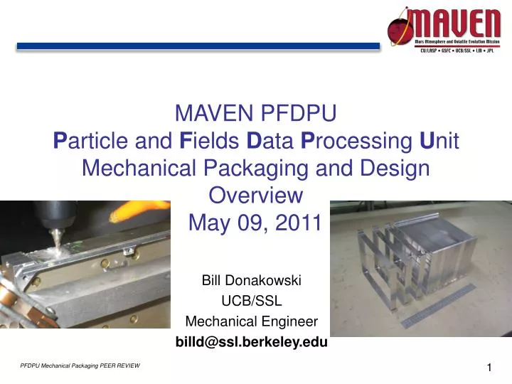
MAVEN PFDPU P article and F ields D ata P rocessing U nit Mechanical Packaging and Design Overview May 09, 2011. Bill Donakowski UCB/SSL Mechanical Engineer billd@ssl.berkeley.edu. PFDPU Overview/Design Drivers. Box to contain consist of 11 separate cards with frames bolted together

E N D
MAVEN PFDPU Particle and Fields Data Processing Unit Mechanical Packaging and Design Overview May 09, 2011 Bill Donakowski UCB/SSL Mechanical Engineer billd@ssl.berkeley.edu
PFDPU Overview/Design Drivers Box to contain consist of 11 separate cards with frames bolted together Each Card contains PCB, connectors, metal frame, EMI shield, and attach fasteners Each card can be removed from Assembly with minimum dis-assembly of box Electrical interconnects as well as external connectors to S/C and individual Instruments Bolted to S/C Panel on one face Frame surface treatment: gold alodined interior, black anodized exterior Box is thermally isolated from S/C Panel High vibe levels: 20.4/14.4 GRMS (Protoflight/Flight)
PFDPU Design Changes from Baseline MDM connectors replace PC104 interboard connectors Interboard connections removed All electrical connections via external connectors and harnesses External harnesses between MDMs on top of box Loss of interboard connectors simplifies assy, alignment, & tooling No need for jigs to align connectors to boards and boards to frames No need for demate or mate tools for connectors Removal of cards does not involve connector demate New EMI shield required outside of MDM Cable harnesses Custom inserts replace nuts holding PCB/frame Custom 4-40 flanged inserts, silver plated Soldered to face of PCB 2 Additional Skewers installed at Sides Box stiffness features incorporated into two Cards MAG and DFB Individual PCBs to be bonded to Frames
PFDPU Overview EMI Shield Ascent Vent Assemblies 11 x Individual Cards in Frames 4 x Threaded Skewers D-Connectors To S/C Interface Bracket to S/C
Cards Stacking 11 Cards: Reg 1, DCB 1, Reg 1, DCB 2, IIB, Sep 1, Sep 2, Mag 1, Mag 2, LPW DFB, LPW BEB 2 Different Card Widths, .700” and 1.15”
Assembly Details EMI Shield Assy MDM & SMA Connectors (harnesses not shown) End Shields (6061 T6) Individual Box Frames (6061 T6 Al) 4 X Threaded Rod Skewers 6 X Attach Feet to S/C Attach Bolts to Box Frames
Typical Card Layer Connectors Attach Screws PCB PC104 Interconnect Traces EMI Shield (PCB FR4/Cu) Aluminum Box Frame Inserts
Interlocking Frame Overview Custom threaded inserts EMI Shield (.031” thick) PCB (.0625” thick) Frame (.100” thick) Interlocking Frame Features
Structural Analysis and Design Ongoing effort with FEM and design to stiffen Boards, Frames, and entire Box Skewers added at center of sides PCBs to be glued to Frames Side shear panels being considered D. Pankow to provide ongoing analysis overview
Status, Ongoing Effort and Challenges • EM Frames fabricated and given to EEs • Fit check OK • Frames and inserts work well • Late change to MDM connectors requires additional work • New connector locations and coordination w/ board layout personnel • New EMI Shield design and Venting Details • New stiffening effort of individual cards by LASP and GSFC • Closer coordination with outside design groups • Verification that Frame interlock scheme and overall fit is adequate (no longer fabricated by same group) • New custom inserts design completed • Addition of two skewers simple • Any new changes a/r by ongoing structural analysis
Back-up: Actions from last PEER Review (May 2010) Hypertronics PC104 issues go away with change to MDMs Four skewers implemented Heat sinking/thermal design ongoing