Download
1 / 19
190 likes | 259 Vues
General Alignment Concept of CMS. Workshop on Tracking in high Multiplicity Environment 2005. T. Lampén. Later: LAS + TBA LAS + “online TBA” (for Pixel): continuous monitoring of larger structures Full TBA with high statistics: alignment of sensors at 10 m level. Day One: assembly + LAS

E N D
General Alignment Concept of CMS Workshop onTracking in high Multiplicity Environment 2005 T. Lampén
Later: LAS + TBA • LAS + “online TBA” (for Pixel): continuous monitoring of larger structures • Full TBA with high statistics: alignment of sensors at 10m level Day One: assembly + LAS -Sensor positions known to ~100m -enables pattern recognition Overall Alignment Strategy Ingredients: • Assembly tolerances and measurements • Laser alignment system (LAS) for large structures,not for pixel! • Track based alignment (TBA)
Estimated misalignments at Day One - much larger than the intrinsic resolution of individual sensors! Misalignments & Assembly Tolerances • Misalignments introduced to reconstruction software • Two scenarios: startup & long-term • Will be refined with alignment studies • Impacts of misalignments to physics -> talk by Nicola de Filippis
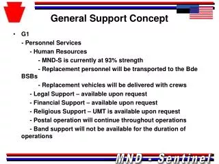
Only global structures aligned. Final alignment of individual units (e.g. silicon sensors) carried out with tracks! Hardware Alignment System Four important ingredients: • Internal • Muon Alignment Barrel • Muon Alignment Endcap • Tracker Alignment • Alignment of Muon w.r.t Tracker (Link System) Monitoring specifications: • Tracker support structures at ~10m • Muon support structures at ~100m • Muon w.r.t Tracker at ~100m Note: Only Strip Tracker and Muon System are included in the Hardware Alignment System. The PIXEL detector will be aligned and monitored with tracks only.
Approaches of Track Based Alignment Cosmic Muons High energetic muons that traverse the detector vertically particular useful for alignment and calibration - barrel region.
Beam Approaches of Track Based Alignment Cosmic Muons High energetic muons that traverse the detector vertically particular useful for alignment and calibration - barrel region. Beam Halo Muons (Hadrons) Machine induced secondary particles that cross the detector almost horizontally particular useful for alignment and calibration - endcap region.
Beam Approaches of Track Based Alignment Cosmic Muons High energetic muons that traverse the detector vertically particular useful for alignment and calibration - barrel region. Triggered by muon chamber RPC's Beam Halo Muons (Hadrons) Machine induced secondary particles that cross the detector almost horizontally particular useful for alignment and calibration - endcap region. Beam Gas Interactions Proton-nucleon interaction in the active detector volume (7TeVEcm=115 GeV) resemble collision events but with a rather soft pT spectrum (pT<2 GeV)
IP5 NHIT1 Rate[Hz] CMS tot ~1800 Muon only ~1800 calorimeter ~ 700 tracker ~ 60 Asymmetric distribution due to access shaft Cosmic Muons Dedicated Trigger in development Started to develop full simulation of Cosmic Muons for IP5 Substantial Expected Rates for E>10 GeV Dedicated cosmic runs expected (e.g. when there is no beam)
Beam Gas Events • Proton-Beam Gas collisions inside the active detector volume, • center-of-mass energy around 115 GeV (7 TeV proton and nucleon) • resemble p-p interactions. Advantages: • Relative large rate already during single beam running Event Topology is very similar to real collision data. Disadvantages: • Soft pT spectrum makes it very hard to trigger and limits its use to inner detector issues (e.g. tracker alignment). Important Issues: • How to trigger these events • Need for a full simulation for beam gas events in CMS Simulation of 114.6 GeV (Ecm2 = 2 mp 7 TeV) center-of-mass fixed target proton-proton collision. Assuming 47.5mb for the proton-nucleon inelastic cross section and Gas-Atom= p-n x A0.7 (A = mass number) Typical Beam Gas: H2, CH4, CO and CO2
Note: Results are strongly dependent on machine parameter settings. These settings are not anymore more fully up-to-date. Improved machine simulations are in preparation! NHIT1 [Hz] CMS tot ~1000 Muon ~ 800 Calo. ~ 800 tracker ~ 200 Beam Halo Muons • Needs also specific Trigger! Muons Hadrons Muons 1kHz Plots based on LHC Project Note 324 (2003) LHC optic 6.4 * in IP1 0.5 m Beam current 0.54 A Rather flat rate 1kHz R in cm R in cm E in GeV Substantial Expected Rates for E>100 GeV However, still significant uncertainties in simulations but probably good enough for a first impression Very interesting for several commissioning efforts of the endcap regions
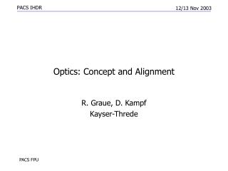
A precision alignment is especially important for high pT muon tracks (TeV region) and to insure efficient muon triggering Alignment of Muon Chambers Muon Endcap Muon Barrel 6000m2 of sensitive area 540 chambers 5 wheels/4 layer each 250 chambers Intrinsic resolution of DT and RPC (Barrel) is ~100m and CSC and RPC (Endcap) ~100-75m Need to align large structures to better than 100m
Alignment of Silicon Tracking Devices • High track efficiency • Precision momentum measurements • Vertex reconstruction • B-tagging … Tracker with its Silicon Strip and PIXEL detectors is the core of the CMS tracking. With roughly 20000 sensors with individual resolutions of ~20m (PIXEL even below 10m) the alignment of these tracking devices is real challenge! Need to align ~200m2 of silicon at the 10m level
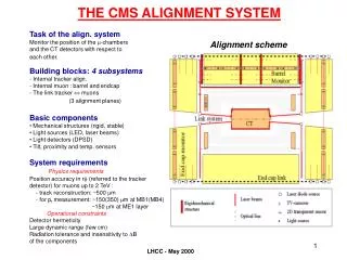
Tracker Alignment Concept in a Nutshell Challenge: Alignment uncertainties must not degrade intrinsic tracker resolution: ≈20m Mechanical Constraints: Sensors on Modules: ≈10m Larger Structures: 0.1-0.5 mm LAS: Aligns global support structures and will monitor relative movements at the level of ≈10m First Data Taking: Laser Alignment Mechanical Constraints ≈100m alignment uncertainties Sufficient for a first efficient pattern recognition. Final Alignment: Use Tracks to achieve the desired level of ≈10m. A combination of track based alignment and laser alignment will insure an accurate monitoring of time dependent alignment effects.
Track based alignment Algorithms • Tracker consist of 20.000 sensors-> 100k x 100k correlation matrix • 4 algorithms implemented • HIP algorithm (Helsinki) • Kalman Filter (Vienna) • Millepede (Hamburg) • Simulated annealing (Lyon) • Ongoing: • Algorithm studies / optimizations • performance studies on (parts of the) full strip/pixel tracker • Studies using the Cosmic Rack (Testbeam data, Cosmics) • Missing: • Realistic scenarios for alignment of the full tracker • Comparisons of the algorithms • Estimates of needed statistics, CPU time etc.
Tests using testbeam and cosmic data ongoing Results from pion test beam data Hits and Impact Points (HIP) algorithm(T. Lampén, V. Karimäki; Helsinki) • Collect a sample of tracks • Align individual sensors independently • Reconstruct tracks and iterate • Low computational cost, 6 x 6 matrix per sensor • Algorithm studied with real data: CRack test beam and cosmic data(8 genuine alignable strip detectors) • Proof of principle for alignment software implementation in CMS software • Larger cosmic data sample expected Average track c2 manual result Particularsensor
Tests using real CMS simulation ongoing Kalman filter algorithm(E. Widl, R. Fruehwirth, W. Adam; Vienna) • Novel approach based on Kalman filter • Update of alignment parameters after each track • Relevant correlations considered, w/o inversion of large matrices • Prior information (e.g. placement constraints) can be used • Algorithm studied with test setup (8 layers, 5 modules each)
Tests using real CMS simulation ongoing Millepede Algorithm(M. Stoye, G. Steinbrueck, V. Blobel; Hamburg) Widely used algorithm Efficient but computationally costly, involves large matrix inversion Alignment studies of simulated Px Barrel Ladders and Strip Barrel Rods, 900k Z-> events ~6k parameters, matrix inversion ~1h, 5 iterations in 5h
Algorithms in development with test beam / cosmic / simulated data Complete alignment simulation for whole Tracker needed Uncovered issues: Results for whole CMS, comparisons of algorithms, required CPU time, statistics etc. More sophisticated alignment tricks – overlaps, vertex constraint, Pt constraint, coverage over two phi, kinematic fit of Z->mm etc. Tracking for beam halo / cosmic muons needed Tracking without pixel and alignment of strip tracker Uncertainties of B field & material budget combination of LAS and TBA, database issues Still lots of things ahead! Prospects of Alignment Work in CMS